Nissan Leaf. Manual - part 95
AV
DIAGNOSIS SYSTEM (AV CONTROL UNIT)
AV-371
< SYSTEM DESCRIPTION >
[NAVIGATION WITH BOSE]
C
D
E
F
G
H
I
J
K
L
M
B
A
O
P
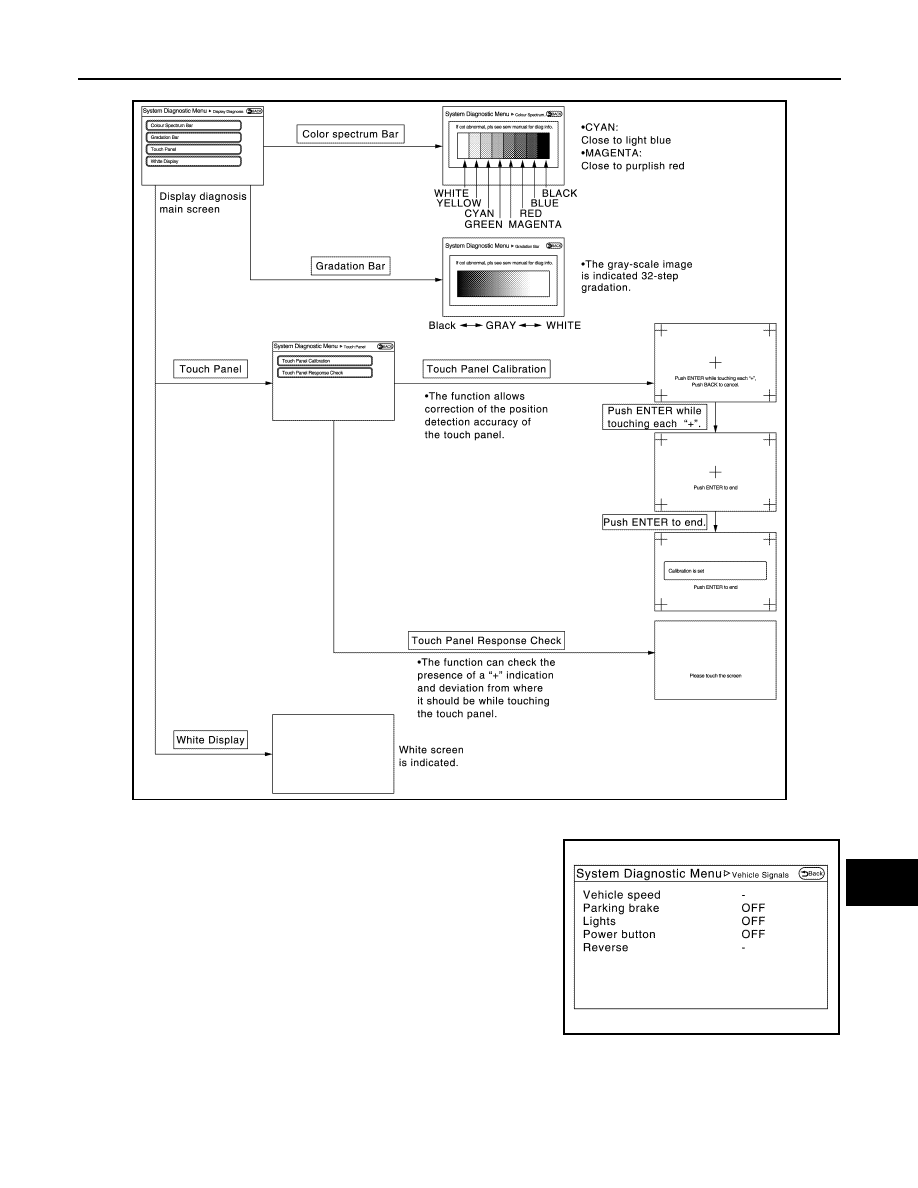
Display Diagnosis
Vehicle Signals
A comparison check can be made of each actual vehicle signal and
the signals recognized by the system.
JSNIA3763ZZ
JSNIA3764ZZ