Nissan Leaf. Manual - part 87
AV
COMPONENT PARTS
AV-339
< SYSTEM DESCRIPTION >
[NAVIGATION WITH BOSE]
C
D
E
F
G
H
I
J
K
L
M
B
A
O
P
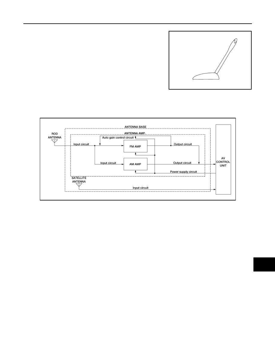
Rod Antenna
A rod antenna is installed to the rear center of the roof.
Antenna Base
• To obtain sufficient reception sensitivity, an antenna amplifier is built into the antenna base.
• Power of the antenna amplifier is supplied from the AV control unit.
• The radio signal received by the rod antenna is input to the antenna base and the antenna signal is amplified
and sent to the AV control unit.
Satellite radio Antenna
• Receives satellite radio waves and outputs it to AV control unit.
Antenna circuit
ALNIA1616ZZ
AWNIA3469GB