Nissan Leaf. Manual - part 32
AV
AV CONTROL UNIT
AV-119
< ECU DIAGNOSIS INFORMATION >
[AUDIO W/O NAVI (FOR MEXICO)]
C
D
E
F
G
H
I
J
K
L
M
B
A
O
P
• When the system is in the fail-safe status after the start of the AV control unit, an error message is not
shown on the display. The MULTI AV system may be rebooted in the fail-safe state. If the fail-safe state is
maintained after the system is rebooted, an applicable message is shown.
CONTROL
When the system is in the fail-safe status at or after start of the AV control unit, the following functions are
restricted.
CANCELLATION CONDITIONS
The fail-safe status is canceled under the following conditions, and then the system returns to the normal
mode.
• When the SD card is not inserted, the SD card is inserted and the power of the AV control unit is turned ON
again.
• When the SD card is not functional at the start of navigation due to a malfunction of the SD card, a normal
SD card is inserted and the power of the AV control unit is turned ON again.
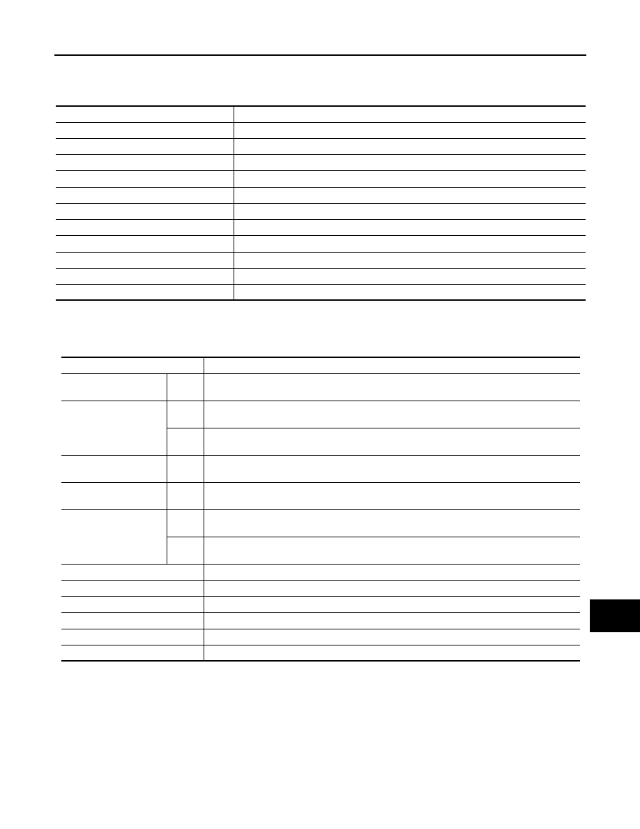
DTC Index
INFOID:0000000010385202
Cause
Display monitor
Malfunction of flash ROM information
TARGET INFO NG
No SD card
NO SD CARD
Unsuccessful security unlock
SD UNLOCK NG
Malfunction of SD card mount
SD INIT NG
Malfunction of SD card access
SD ACCESS NG
No program data
NO NAVI-2 DATA
Malfunction of program data (SUM NG)
NAVI-2DATA READ NG
Inconsistent program version (Flash/SD)
NAVI VERSION NG
Difference of map destination
DIFFERENT MAP CODE
Not compliant with map database version
MAP DATA BASE UNMATCH
Malfunction of navigation
NAVI STARTUP NG
Function
In fail-safe mode
A/C
Dis-
play
No display (fail-safe status display)
Audio
Opera-
tion
Mute audio
Dis-
play
No display (fail-safe status display)
Hands-free phone
Opera-
tion
It cannot be operated
Navigation
Opera-
tion
It cannot be operated
Display
Opera-
tion
Open/close operation is available
Dis-
play
Fail-safe factors are displayed
Self-diagnosis
It cannot be diagnosed
CONSULT diagnosis
It cannot be diagnosed
AV communication diagnosis
It cannot be diagnosed
Frequency transmission for VCM
Normal
SD read access
Access cannot be gained.
SD write access
Access cannot be gained.