Nissan Primera P11. Manual - part 538


  Index      Nissan     Nissan Primera P11 (2001 year) - Service and Repair Manual


Search            


Content   ..  536  537  538  539   ..


Nissan Primera P11. Manual - part 538


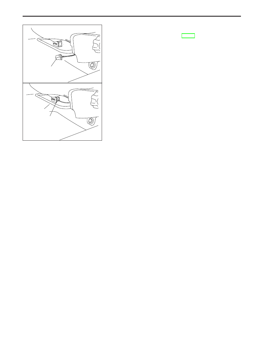
6. Connect side air bag module connector.
7. Connect both battery cables.
8. Go to “SRS Operation Check”, RS-37 and perform self-diag-

nosis to ensure entire SRS operates properly. (Use CON-
SULT-II or AIR BAG warning lamp).

NRS082

Connector

Connector

SUPPLEMENTAL RESTRAINT SYSTEM (SRS)

Installation — Side Air Bag Module (Cont’d)

RS-21

Disposal of Air Bag Module and Seat Belt
Pre-tensioner

Before disposing of air bag module and seat belt pre-tensioner, or vehicles equipped with such systems,
deploy the systems. If such systems have already been deployed due to an accident, dispose of as
indicated in “DISPOSING OF AIR BAG MODULE AND SEAT BELT PRE-TENSIONER” (RS-27).

When deploying the air bag module and seat belt pre-tensioner, always use the Special Service Tool;
Deployment tool KV99106400.

When deploying the air bag module and seat belt pre-tensioner, stand at least 5 m (16 ft) away from
deployment component.

When deploying air bag module and seat belt pre-tensioner a fairly loud noise is made, followed by
smoke being released. The smoke is not poisonous, however, be careful not to inhale smoke since it
irritates the throat and can cause choking.

Always activate one air bag module at a time.

Due to heat, leave air bag module unattended for more than 30 minutes after deployment. Also leave
seat belt pre-tensioner unattended for more than 10 minutes after deployment.

Be sure to wear gloves when handling a deployed air bag module and seat belt pre-tensioner.

Never apply water to a deployed air bag module and seat belt pre-tensioner.

Wash your hands clean after finishing work.

Place the vehicle outdoors with an open space of at least 6 m (20 ft) on all sides when deploying air
bag module and seat belt pre-tensioner while mounted in vehicle.

Use a voltmeter to make sure the vehicle battery is fully charged.

Do not dispose of the air bag module and seat belt pre-tensioner un-deployed.

CHECKING DEPLOYMENT TOOL

Connecting to battery

CAUTION:

The battery must show voltage of 9.6V or more.
Remove the battery from the vehicle and place it on dry wood
blocks approximately 5 m (16 ft) away from the vehicle.

Wait 3 minutes after the vehicle battery is disconnected
before proceeding.

Connect red clip of deployment tool to battery positive termi-
nal and black clip to negative terminal.

Make sure the polarity is correct. The right side lamp in the
tool, marked “deployment tool power”, should glow with a
green light. If the right side lamp glows red, reverse the
connections to the battery.

SRS019-A

Red

Black

Deployment tool
(KV99106400)

SUPPLEMENTAL RESTRAINT SYSTEM (SRS)

RS-22

Deployment tool check

Press the deployment tool push button to the “ON” position. The
left side lamp in the tool, marked “air bag connector voltage”
should illuminate. If it does not illuminate, replace the tool.

Air bag deployment tool lamp illumination chart
(Battery connected)

Switch operation

Left side lamp, green*

“AIR BAG CONNECTOR

VOLTAGE”

Right side lamp, green*

“DEPLOYMENT TOOL

POWER”

OFF

OFF

ON

ON

ON

ON

*: If this lamp glows red, the tool is connected to the battery incorrectly.

Reverse the connections and make sure the lamp glows green.

DEPLOYMENT PROCEDURES FOR AIR BAG
MODULE AND SEAT BELT PRE-TENSIONER
(OUTSIDE OF VEHICLE)

Unless the vehicle is being scrapped, deploying the air bag mod-
ule and seat belt pre-tensioner in the vehicle is not recom-
mended. This may cause damage to the vehicle interior.
Anchor air bag module and seat belt pre-tensioner in a vise
secured to a firm foundation during deployment.

Deployment of Driver’s Air Bag Module (Outside of
vehicle)

1. Using wire, secure air bag module to air bag module bracket

[SST: KV99105300] at two places.

CAUTION:

Use wire of at least 1 mm (0.04 in) diameter.
2. Attach tightly the air bag module bracket [SST: KV99105300]

with air bag module in a vise.

3. Connect deployment tool [SST: KV99106400] to air bag mod-

ule connector.

4. Connect red clip of deployment tool to battery positive termi-

nal and black clip to negative terminal.

5. The lamp on the right side of the tool, marked “deployment

tool power”, should glow green, not red.

6. Press the button on the deployment tool. The left side lamp

on the tool, marked “air bag connector voltage”, will illuminate
and the air bag module will deploy.

CAUTION:

When deploying the air bag module, stand at least 5 m (16 ft)
away from the air bag module.

SBF266H

Lamp

Push

SRS233

Wire

Air bag module
bracket
[KV99105300]

Wire

SRS234

Deployment tool
[KV99106400]

Air bag module bracket
[KV99105300]

Wire

Air bag module
connector

Wire

SRS235

Air bag module

Deployment tool
(KV99106400)

SUPPLEMENTAL RESTRAINT SYSTEM (SRS)

Disposal of Air Bag Module and Seat Belt
Pre-tensioner (Cont’d)

RS-23

Deployment of Passenger’s Air bag Module (outside
of vehicle)

1. Make an 8.5 mm (0.335 in) diameter hole in air bag module

bracket [SST: KV99105300] at the position as shown in the
left figure.

2. Attach tightly the air bag module bracket [SST: KV99105300]

in a vise.

3. Match the two holes in air bag module bracket (held in vise)

and passenger’s air bag module and fix them with two bolts
[M8 x 25 - 30 mm (0.98 - 1.18 in)].

CAUTION:

If a gap exists between passenger’s air bag module and air
bag module bracket, use a piece of wood inserted in the gap
to stabilize the air bag module.

4. Connect deployment tool adapter [SST: KV99108300] to

deployment tool [SST: KV99106400] connector and air bag
module connector.

5. Connect red clip of deployment tool to battery positive termi-

nal and black clip to negative terminal.

6. The lamp on the right side of the tool, marked “deployment

tool power”, should glow green, not red.

7. Press the button on the deployment tool. The left side lamp

on the tool, marked “air bag connector voltage”, will illuminate
and the air bag module will deploy.

CAUTION:

When deploying the air bag module, stand at least 5 m (16 ft)
away from the air bag module and do not stand on the
deploying side.

Deployment of Side Air bag Module (outside of
vehicle)

1. Make 6.5 mm (0.256 in) diameter holes in air bag module

bracket [SST: KV99105300] at the position as shown on the
left figure.

NRS084

15 (0.59)

15 (0.59)

8.5 (0.335 dia.)

144 (5.67)

Air bag module bracket
[KV99105300]

Unit: mm (in)

NRS022

Air bag
bracket
[KV99105300]

Bolt
M 8 x 25 - 30 mm
(0.98 - 1.18 in)

.

Deployment tool adapter
[KV99108300]

Deployment tool
[KV99106400]

NRS023

SRS020-B

Air bag module

Deployment tool
[KV99106400]

SRS490

.

13 (0.51)

Unit: mm (in)

Air bag module bracket
[KV99105300]

6.5 (0.256) dia.

(2.76)

(3.15)

SUPPLEMENTAL RESTRAINT SYSTEM (SRS)

Disposal of Air Bag Module and Seat Belt
Pre-tensioner (Cont’d)

RS-24


Content   ..  536  537  538  539   ..