Nissan Primera P11. Manual - part 486
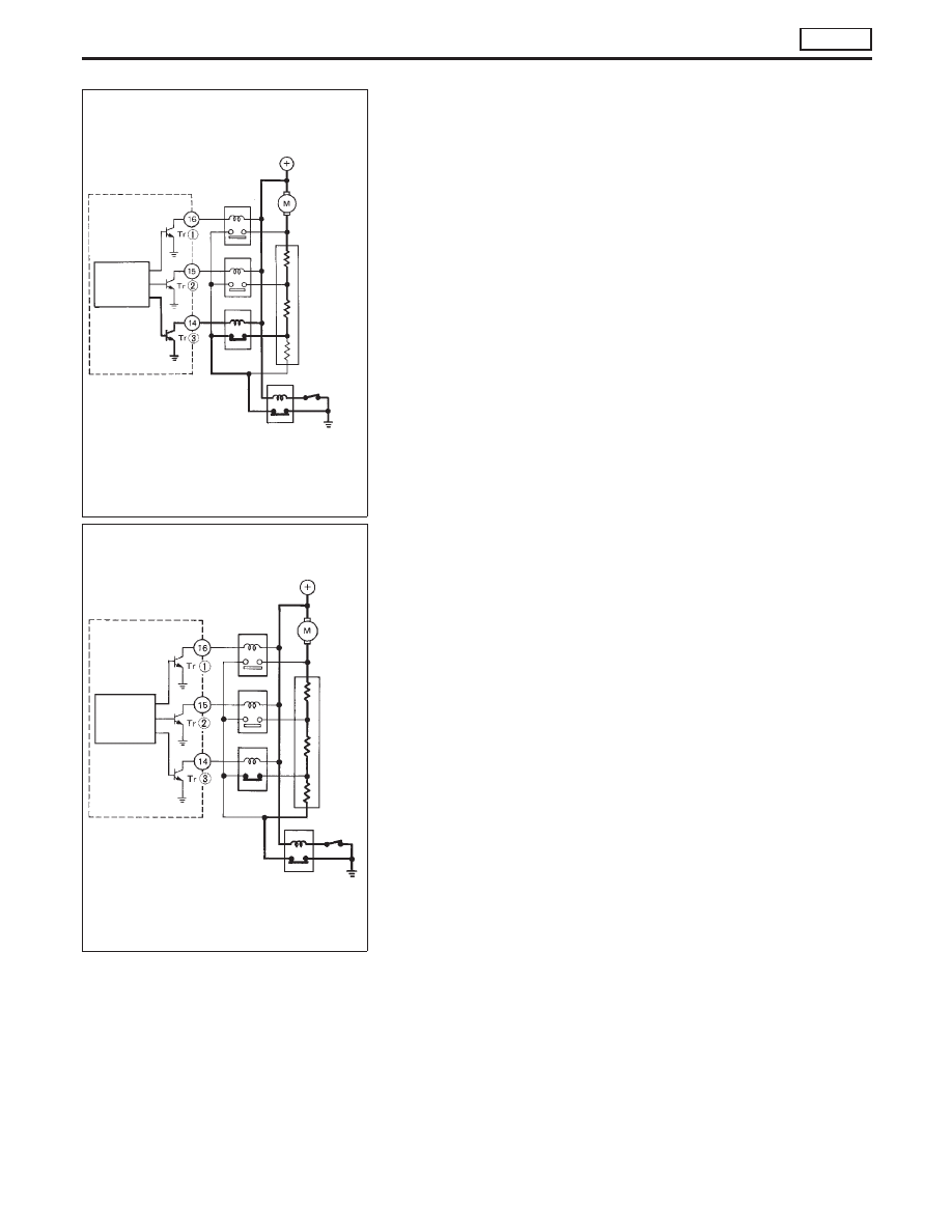
(2) When set to HI
The air flow volume arithmetic circuit gives current to Tr
p
1
,
which turns the HI relay on. Thus, the blower motor rotates
in the HI condition. Also, Tr
p
2
and Tr
p
3
are receiving cur-
rent and as a result the ML and MH relays are on.
(3) When set to LO
The air flow volume arithmetic circuit does not give any cur-
rent to Tr
p
1
,
p
2
nor
p
3
.
Only the LO relay turns on and so the blower motor rotates
in the LO condition.
SHA574CA
Air flows
volume
arithmetic
circuit
HI
relay
MH relay
ML relay
Blower
motor
Resistor
Fan switch
(AUTO)
LO relay
Auto amp.
SHA576CA
Air flows
volume
arithmetic
circuit
HI
relay
MH relay
ML relay
Blower
motor
Resistor
Fan switch
(AUTO)
LO relay
Auto amp.
SYSTEM DESCRIPTION
AUTO
Control System Output Components (Cont’d)
HA-97