Nissan Primera P11. Manual - part 481
Diagnostic Procedure 14
SYMPTOM: Thermal transmitter circuit is open or shorted.
Note
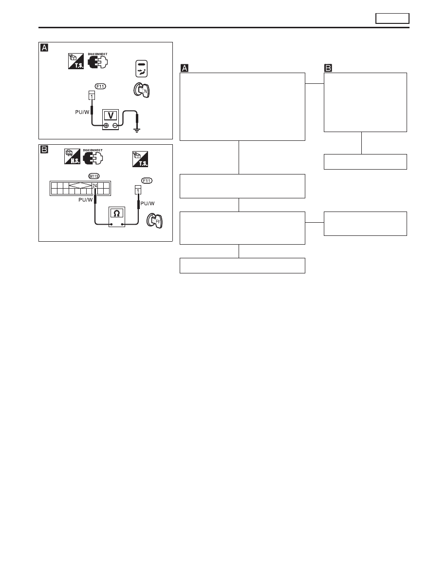
CHECK THERMAL TRANSMITTER
CIRCUIT.
Disconnect thermal transmitter harness
connector.
Do approx.
12 volts
exist between ther-
mal transmitter harness terminal No.
p
1
and body ground?
OK
E
NG
Check circuit continuity
between thermal trans-
mitter harness terminal
No.
p
1
and control
panel harness terminal
No.
p
24
.
Replace control panel
Disconnect control panel harness con-
nector.
CHECK THERMAL TRANSMITTER.
(Refer to “THERMAL TRANSMITTER
CHECK” in EL section.)
OK
E
NG
Replace thermal trans-
mitter.
Replace control panel
Note:
If the result is NG or No after checking circuit continuity, repair harness or
connector.
YHA292
Thermal transmitter
connector
YHA293
Control panel
connector
Thermal transmitter
connector
H
H
H
H
TROUBLE DIAGNOSES
AUTO
HA-77