Nissan Primera P11. Manual - part 467


  Index      Nissan     Nissan Primera P11 (2001 year) - Service and Repair Manual


Search            


Content   ..  465  466  467  468   ..


Nissan Primera P11. Manual - part 467


Control Operation

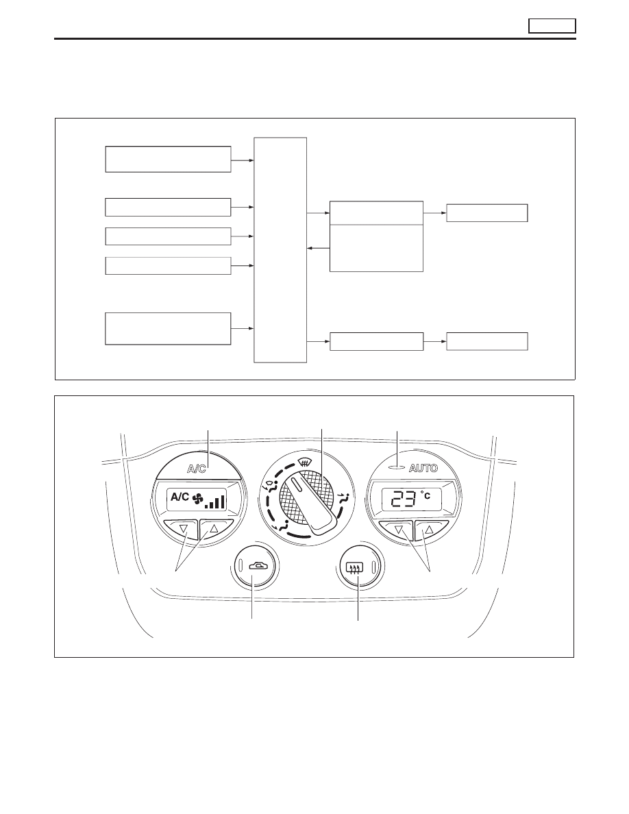
The control system consist of a) input sensors and switches, b) the automatic amplifier (microcomputer), and
c) outputs.
The relationship of these components is shown in the diagram below:

KHA111

Control unit

Set temperature Control
(Potentio temperature control)

Ambient sensor

In-vehicle sensor

Sunload sensor

Thermal transmitter

Automatic
amplifier
(Micro- com-
puter)

Air mix door motor

PBR
(Potentio Balance Resis-
tor)built-into air mix door
motor

Fan

Air mix door

Blower motor

KHA112

Auto air conditioner

Air conditioner switch

Mode control knob

Auto switch

Fan control

Recirculation
switch

Rear window
defogger switch

Temperature control
switch (PTC)

DESCRIPTION

AUTO

HA-21

FAN CONTROL SWITCH

Manual control of the blower speed. Four speeds are available for manual control (as shown on the display
screen):
low

I

, medium low

I

I

, medium high

I

I

I

, high

I

I

I

I

MODE CONTROL KNOB

This knob controls outlet air flow.
In “DEF” (

) mode, the intake door is set to “FRESH”, and the A/C on.

AUTO SWITCH

The air mix door, and blower speed are automatically controlled so that the in-vehicle temperature will reach,
and be maintained at the set temperature selected by the operator.

TEMPERATURE CONTROL SWITCH (POTENTIO TEMPERATURE CONTROL)

Increases or decreases the set temperature.

RECIRCULATION (REC) SWITCH

OFF position: Outside air is drawn into the passenger compartment.
ON position: Interior air is recirculated inside the vehicle.
RECIRC is canceled when DEF mode is selected.

AIR CONDITIONING SWITCH

The air conditioner switch controls the A/C system. When the switch is depressed with the fan ON, the
compressor will turn ON. The display screen indicates “A/C”.
A/C switch will turn on when DEF mode is selected.
The air conditioner cooling function operates only when the engine is running.

DESCRIPTION

AUTO

Control Operation (Cont’d)

HA-22

Discharge Air Flow

KHA113

p

1

: Ventilation

p

2

: Foot

p

3

: Defroster

: Air flow in REC position

p

3

p

3

p

3

p

3

Vent

Foot

p

3

To defroster

p

2

To floor

p

2

To floor

Foot and defroster

p

3

To defroster

p

2

To floor

p

2

To floor

Outside air

Defroster

p

3

To defroster

Outside air

p

1

To ventilator

Defroster door

Fresh vent door

Heater core

Intake air

Intake door

Air mix door

Floor door

Ventilator door

Bi-level

p

1

To ventilator

p

2

To floor

p

2

To floor

This illustration is for LHD models.
The layout for RHD models issymmetrically opposite.

Outside air

Air passed through heater core

Mixed air (

+

)

Air not passed through heater core

p

2

Outside air

DESCRIPTION

AUTO

HA-23

Operational Check

The purpose of the operational check is to confirm that the sys-
tem operates as it should. The systems which are checked are
the blower, mode (discharge air), intake air, temperature
decrease, temperature increase.

CONDITIONS:

Engine running at normal operating temperature.

PROCEDURE:

1. Check blower

1) Turn fan control knob to 1-speed.

Blower should operate on 1-speed.

2) Then turn fan control knob to 2-speed.
3) Continue checking blower speed until all four speeds are

checked.

4) Leave blower on 4-speed.

2. Check discharge air

1) Turn mode control knob.

2) Confirm that discharge air comes out according to the air

distribution table at left.
Refer to “Discharge Air Flow” in “DESCRIPTION” (HA-23).

KHA106

KHA107

KHA032

Discharge airflow

Switch

mode/

indicator

Airoutlet/distribution

Face

Foot

Defroster

100%

60%

40%

15%*

65%

20%

15%*

55%

30%

15%*

85%

* Face air from SIDE VENT only

TROUBLE DIAGNOSES

HEATER

HA-24


Content   ..  465  466  467  468   ..