Nissan Primera P11. Manual - part 464
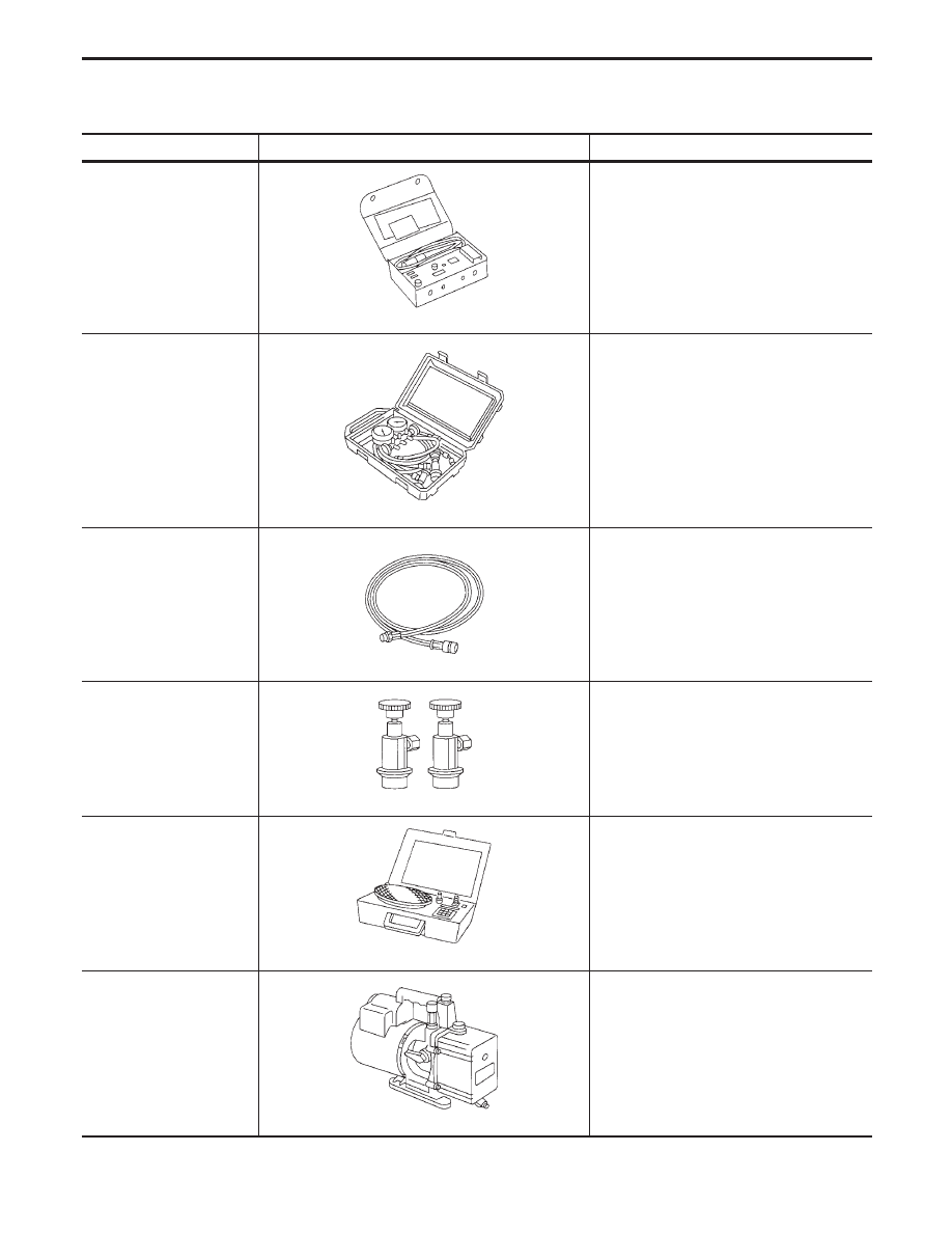
Tool name
Description
Note
Electrical leak detector
NT198
Power supply:
●
DC 12 V (Cigarette lighter)
Manifold gauge set (with
hoses and couplers)
NT199
Identification:
●
The gauge face indicates R-134a.
Fitting size: Thread size
●
1/2”-16 ACME
Service hoses
●
High side hose
●
Low side hose
●
Utility hose
NT201
Hose color:
●
Low hose: Blue with black stripe
●
High hose: Red with black stripe
●
Utility hose: Yellow with black stripe or
green with black stripe
Hose fitting to gauge:
●
1/2”-16 ACME
Service couplers
●
High side coupler
●
Low side coupler
NT202
Hose fitting to service hose:
●
M14 x 1,5 fitting is optional or perma-
nently attached.
Refrigerant weight scale
NT200
For measuring of refrigerant
Fitting size: Thread size
●
1/2”-16 ACME
Vacuum pump
(Including the isolator
valve)
NT203
Capacity:
●
Air displacement: 4 CFM
●
Micron rating: 20 microns
●
Oil capacity: 482 g (17 oz)
Fitting size: Thread size
●
1/2”-16 ACME
PRECAUTIONS AND PREPARATION
HFC-134a (R-134a) Service Tools and
Equipment (Cont’d)
HA-9