Nissan Primera P11. Manual - part 428


  Index      Nissan     Nissan Primera P11 (2001 year) - Service and Repair Manual


Search            


Content   ..  426  427  428  429   ..


Nissan Primera P11. Manual - part 428


4.

Measure outside diameter “Dp” of crankshaft pin journal.

5.

Calculate connecting rod bearing clearance.

Connecting rod bearing clearance = C − Dp

Standard:

0.031 - 0.055 mm (0.0012 - 0.0022 in)

I

If it exceeds the limit, replace the bearing.

I

If crankshaft pin journal is worn or shows any abnormality,
regrind crank pin and use undersized bearings to maintain the
specified oil clearance.

I

Refer to SDS for regrinding diameter of crankshaft pin and
available service parts (EM-200).

I

When regrinding crankshaft pin, do not grind fillet-roll.

Selective connecting rod bearing

I

If either bearings or crankshaft are being replaced with new
ones, select connecting rod bearings according to the follow-
ing table. Grade numbers are punched in either Arabic or
Roman numerals.

Crankshaft pin journal grade number

0

1

2

Connecting rod bearing grade
number

0

1

2

Identification color

Grade 0: Black
Grade 1: Yellow
Grade 2: Blue

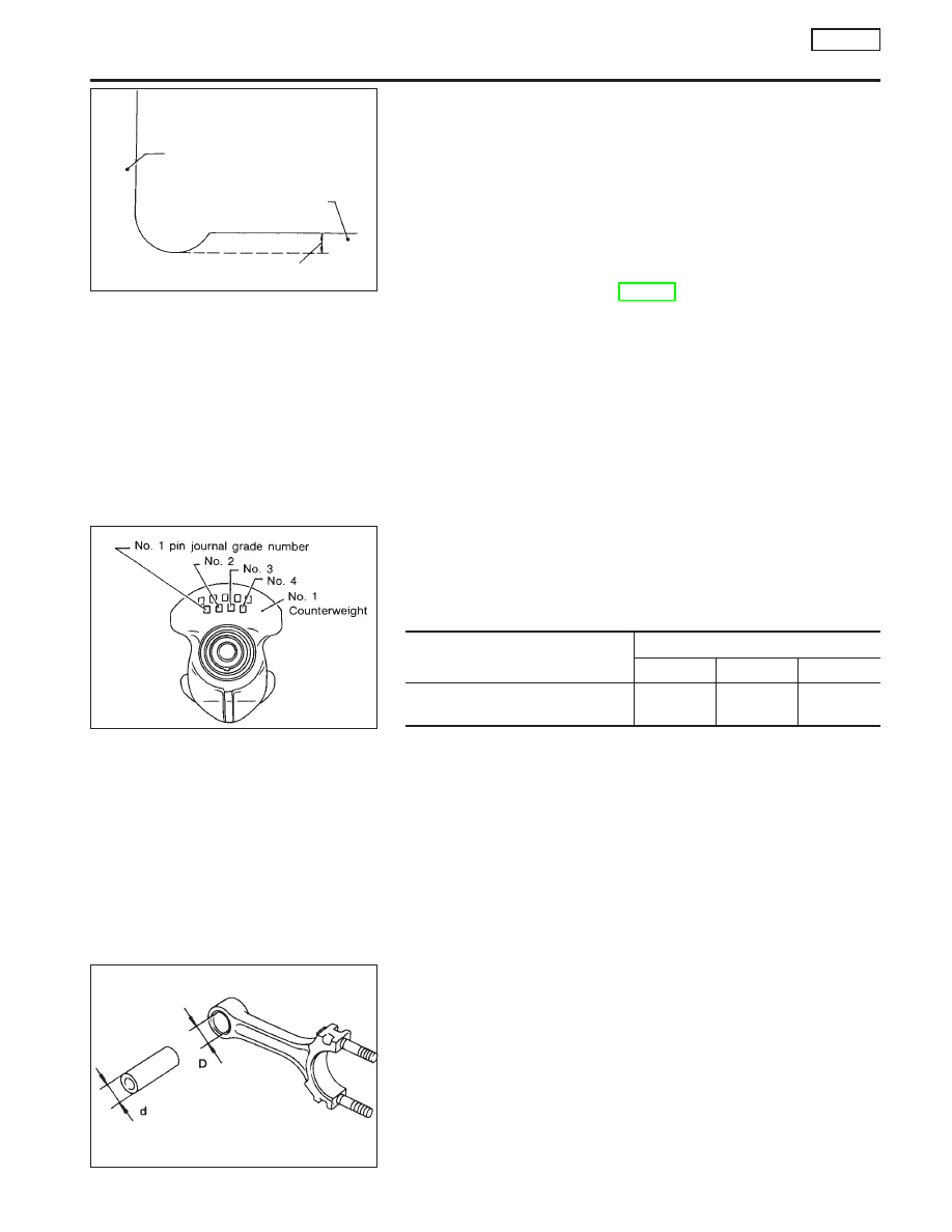
CONNECTING ROD AND PISTON PIN CLEARANCE
(Small end)

Clearance (D − d):

0.025 - 0.044 mm (0.0010 - 0.0017 in)

I

If clearance exceeds the specifications, replace the bearing.

SEM361D

Counter weight

Pin journal

.

Maintain more than 0.13 mm (0.051 in)

SEM705D

SEM575B

Clearance = D − d

CYLINDER BLOCK

CD20T

Inspection (Cont’d)

EM-171

Bearing replacement

I

Remove bearing with a suitable tool.

Do not scratch inner surface of connecting rod.

1.

Install new bearing with oil holes aligned correctly.

2.

Ream bore using a suitable tool.

Ream bore:

28.025 - 28.038 mm (1.1033 - 1.1039 in)

CONNECTING ROD BEND AND TORSION

Bend and torsion [per 100 mm (3.94 in) length]:

Bend Less than 0.025 mm (0.0010 in)
Torsion Less than 0.025 mm (0.0010 in)

CRANKSHAFT

1.

Check crankshaft journals and pins for score, bias, wear or
cracks. If faults are minor, correct with fine emery paper.

2.

Check journals and pins with a micrometer for taper and out-
of-round.

Out-of-round (X − Y):

Less than 0.005 mm (0.0002 in)

Taper (A − B):

Less than 0.005 mm (0.0002 in)

3.

Check crankshaft runout.

Runout (Total indicator reading):

Less than 0.05 mm (0.0020 in)

SEM906

SEM907

EM133

SEM316A

Taper:

Out-of-round:

.

SEM601A

CYLINDER BLOCK

CD20T

Inspection (Cont’d)

EM-172

CYLINDER BLOCK DISTORTION

Clean upper face of cylinder block and measure the distortion.

Limit:

0.10 mm (0.0039 in)

If out of specification, resurface it.
The resurfacing limit of cylinder block is determined by cylin-
der head resurfacing in an engine.

Amount of cylinder head resurfacing is “A”.
Amount of cylinder block resurfacing is “B”.

The maximum limit is as follows:

A + B = 0.1 mm (0.004 in)

Nominal cylinder block height from crankshaft center:

227.75 - 227.85 mm (8.9665 - 8.9705 in)

If necessary, replace cylinder block.

CYLINDER BORE

1.

Check for scratches or seizure. If seizure is found, hone bore.

2.

Using a bore gauge, measure cylinder bore for wear, out-of-
round or taper.

Standard bore diameter:

84.500 - 84.550 mm (3.3268 - 3.3287 in)

Unit: mm (in)

Bore wear limit

0.2 (0.008)

Out-of-round (X − Y) standard

0.015 (0.0006)

Taper (A − B) standard

0.010 (0.0004)

If it exceeds the limit, rebore all four cylinders. Replace cylinder
block if necessary.
If cylinder block or piston is replaced, match piston grade with
grade number on cylinder block upper surface.

SEM655A

Measuring points

Warpage of surface:

Less than 0.1 mm (0.004 in)

NEM210

H

=

227.75-227.85

mm

(8.9665-8.9705

in)

SEM704DA

CYLINDER BLOCK

CD20T

Inspection (Cont’d)

EM-173

Reboring

1.

The size to which cylinders must be honed, is determined by
adding piston-to-cylinder clearance to the piston skirt diameter
“A”.

Dimension “a”:

Approximately 62 mm (2.44 in)

Rebored size calculation

D = A + B − C = A + [0.03 to 0.05 mm
(0.0012 to 0.0020 in)]

where,

D: Honed diameter
A: Skirt diameter as measured
B: Piston-to-wall clearance
C: Machining allowance

0.02 mm (0.0008 in)

2.

Install main bearing caps and tighten bolts to the specified
torque. This will prevent distortion of cylinder bores.

3.

Cut cylinder bores in the order of 2-4-1-3.

Do not cut too much out of the cylinder bore at a time. Cut only
0.05 mm (0.0020 in) or so in diameter at a time.
4.

Hone the cylinders to the required size referring to SDS (EM-
199).

5.

Measure the finished cylinder bore for out-of-round and taper.

Measurement of a just machined cylinder bore requires
utmost care since it is expanded by cutting heat.

PISTON-TO-BORE CLEARANCE

Using micrometer

1.

Measure piston and cylinder bore diameter.

Piston diameter “A”:

Refer to SDS (EM-199).

Measuring point “a” (Distance from the bottom):

Approximately 62 mm (2.44 in)

Bore diameter “D”:

Refer to SDS (EM-199).

Measuring point (Distance from the top):

Approximately 70 mm (2.76 in)

2.

Check that piston clearance is within the specification.

Piston clearance (D − A):

0.030 - 0.050 mm (0.0012 - 0.0020 in)

SEM176B

Piston grade number

Front

SEM904-A

CYLINDER BLOCK

CD20T

Inspection (Cont’d)

EM-174


Content   ..  426  427  428  429   ..