Nissan Primera P11. Manual - part 400


  Index      Nissan     Nissan Primera P11 (2001 year) - Service and Repair Manual


Search            


Content   ..  398  399  400  401   ..


Nissan Primera P11. Manual - part 400


4.

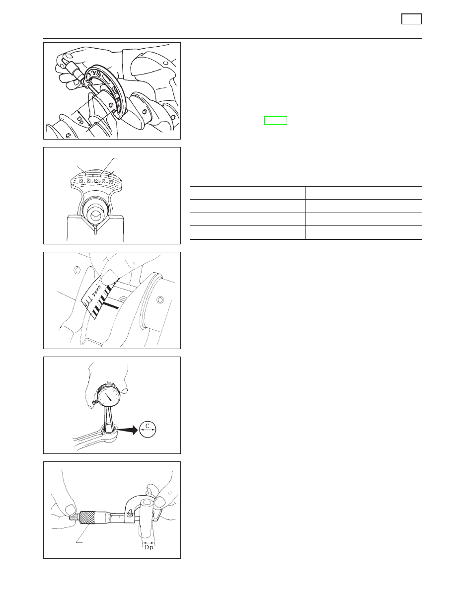
Measure outer diameter “Dp” of each crankshaft pin journal.

5.

Calculate connecting rod bearing clearance.

Connecting rod bearing clearance = C − Dp

Standard: 0.014 - 0.039 mm (0.0006 - 0.0015 in)
Limit: 0.1 mm (0.004 in)

If it exceeds the limit, replace bearing.
If clearance cannot be adjusted using any standard bearing
grade, grind crankshaft journal and use undersized bearing.
Refer to step 5, EM-57.

I

If a new bearing, crankshaft or connecting rod is replaced,
select connecting rod bearing according to the following table.

Connecting rod bearing grade number:
These numbers are punched in either Arabic or Roman numerals.

Crankshaft pin journal grade number

Connecting rod bearing grade color

0

1

Brown

2

Green

Method B (Using Plastigage)

CAUTION:

I

Do not turn crankshaft or connecting rod while Plastigage
is being inserted.

I

If incorrect bearing clearance exists, use a thicker or
undersized main bearing to ensure specified clearance.

CONNECTING ROD BUSHING CLEARANCE (Small end)

NCEM0026S09

1.

Measure inner diameter “C” of bushing.

2.

Measure outer diameter “Dp” of piston pin.

3.

Calculate connecting rod bushing clearance.

Connecting rod bushing clearance = C − Dp

Standard:

0.005 - 0.017 mm (0.0002 - 0.0007 in)

Limit:

0.023 mm (0.0009 in)

If it exceeds the limit, replace connecting rod assembly or
connecting rod bushing and/or piston pin.

AEM028

SEM437CA

Crankshaft pin journal
grade number

No. 1

No. 4

EM142

AEM029

AEM030

Micrometer

CYLINDER BLOCK

QG

Inspection (Cont’d)

EM-59

REPLACEMENT OF CONNECTING ROD BUSHING
(Small end)

NCEM0026S10

1.

Drive in small end bushing until it is flush with end surface of
rod.

Be sure to align the oil holes.
2.

Ream the bushing so that clearance with piston pin is within
specification.

Clearance between connecting rod bushing and pis-
ton pin:

0.005 - 0.017 mm (0.0002 - 0.0007 in)

FLYWHEEL/DRIVE PLATE RUNOUT

NCEM0026S12

Runout (Total indicator reading):

Flywheel

Less than 0.15 mm (0.0059 in)

CAUTION:

I

Do not allow any magnetic materials to contact the ring
gear teeth and rear plate.

I

Do not resurface flywheel. Replace as necessary.

Assembly

NCEM0027

PISTON

NCEM0027S01

1.

Install new snap ring on one side of piston pin hole.

2.

Heat piston to 60 to 70°C (140 to 158°F) and assemble piston,
piston pin, connecting rod and new snap ring.

I

Align the direction of piston and connecting rod.

I

Numbers stamped on connecting rod and cap correspond
to each cylinder.

I

After assembly, make sure connecting rod swings
smoothly.

3.

Set piston rings as shown.

CAUTION:

I

When piston rings are not replaced, make sure that piston
rings are mounted in their original position.

I

Install new piston rings either side up if there is no punch
mark.

SEM062A

Align.

SEM931F

Dial gauge

SEM166B

SEM932F

Piston pin
grade number

Oil hole

Cylinder
number

Front

Front mark

Piston grade
number

SEM965E

Punchmark side up
(if mark is present.)

CYLINDER BLOCK

QG

Inspection (Cont’d)

EM-60

I

Align piston rings so that end gaps are positioned as
shown.

CRANKSHAFT

NCEM0027S02

1.

Install signal plate to crankshaft.

2.

Set main bearings in their proper positions on cylinder block
and main bearing cap.

I

Confirm that correct main bearings are selected by using
Method A or Method B. Refer to EM-57.

I

Apply new engine oil to bearing surfaces.

3.

Install crankshaft and main bearing caps and tighten bolts to
the specified torque.

I

Apply new engine oil to the bolt thread and seat surface.

I

Prior to tightening bearing cap bolts, shift crankshaft back
and forth to properly seat the bearing caps.

I

Tighten bearing cap bolts gradually in two or three stages.
Start with center bearing and move outward as shown in
figure.

I

After securing bearing cap bolts, make sure crankshaft
turns smoothly by hand.

SEM160B

Oil ring
expander

Top ring
Oil ring
upper rail

Oil ring
lower rail

2nd ring

Engine
front

SEM934F

Crankshaft

Signal plate

Duel pin

SEM366E

Oil hole

Oil groove

Front

SEM420C

Identification No.

Cap

Engine front

SEM933F

Engine
front

Tighten in numerical order.

CYLINDER BLOCK

QG

Assembly (Cont’d)

EM-61

4.

Measure crankshaft end play.

Crankshaft end play:

Standard

0.060 - 0.260 mm (0.0024 - 0.0102 in)

Limit

0.3 mm (0.012 in)

If beyond the limit, replace thrust bearing with new ones.

5.

Install connecting rod bearings in connecting rods and con-
necting rod caps.

I

Confirm that correct bearings are used. Refer to EM-58.

I

Install bearings so that oil hole in connecting rod aligns
with oil hole of bearing.

I

Apply new engine oil to bolt threads and bearing surfaces.

6.

Install pistons with connecting rods.

a.

Install them into corresponding cylinders with Tool.

I

Make sure connecting rod does not scratch cylinder wall.

I

Make sure connecting rod bolts do not scratch crankshaft
pin journals.

I

Arrange so that front mark on piston head faces engine.

I

Apply new engine oil to piston rings and sliding surface
of piston.

b.

Install connecting rod caps.
Apply new engine oil to bolt threads and nut seating surfaces.
Tighten connecting rod cap nuts in the following procedure:

I

Tighten to 13.72 to 15.68 N

m (1.399 to 1.599 kg-m, 10.120

- 11.566 ft-lb).

I

Turn nuts to 35° to 40° degrees clockwise with an angle
wrench. If an angle wrench is not available, tighten nuts to
23 to 28 N

m (2.3 to 2.9 kg-m, 17 to 21 ft-lb).

7.

Measure connecting rod side clearance.

Connecting rod side clearance:

Standard

0.200 - 0.470 mm (0.0079 - 0.0185 in)

Limit

0.5 mm (0.0205 in)

If beyond the limit, replace connecting rod and/or crank-
shaft.

SEM116F

SEM168D

Align oil hole.

SEM942F

Piston ring compressor
EM03470000

SEM943F

KV10112100

SEM935F

Feeler gauge

CYLINDER BLOCK

QG

Assembly (Cont’d)

EM-62


Content   ..  398  399  400  401   ..