Nissan Primera P11. Manual - part 393
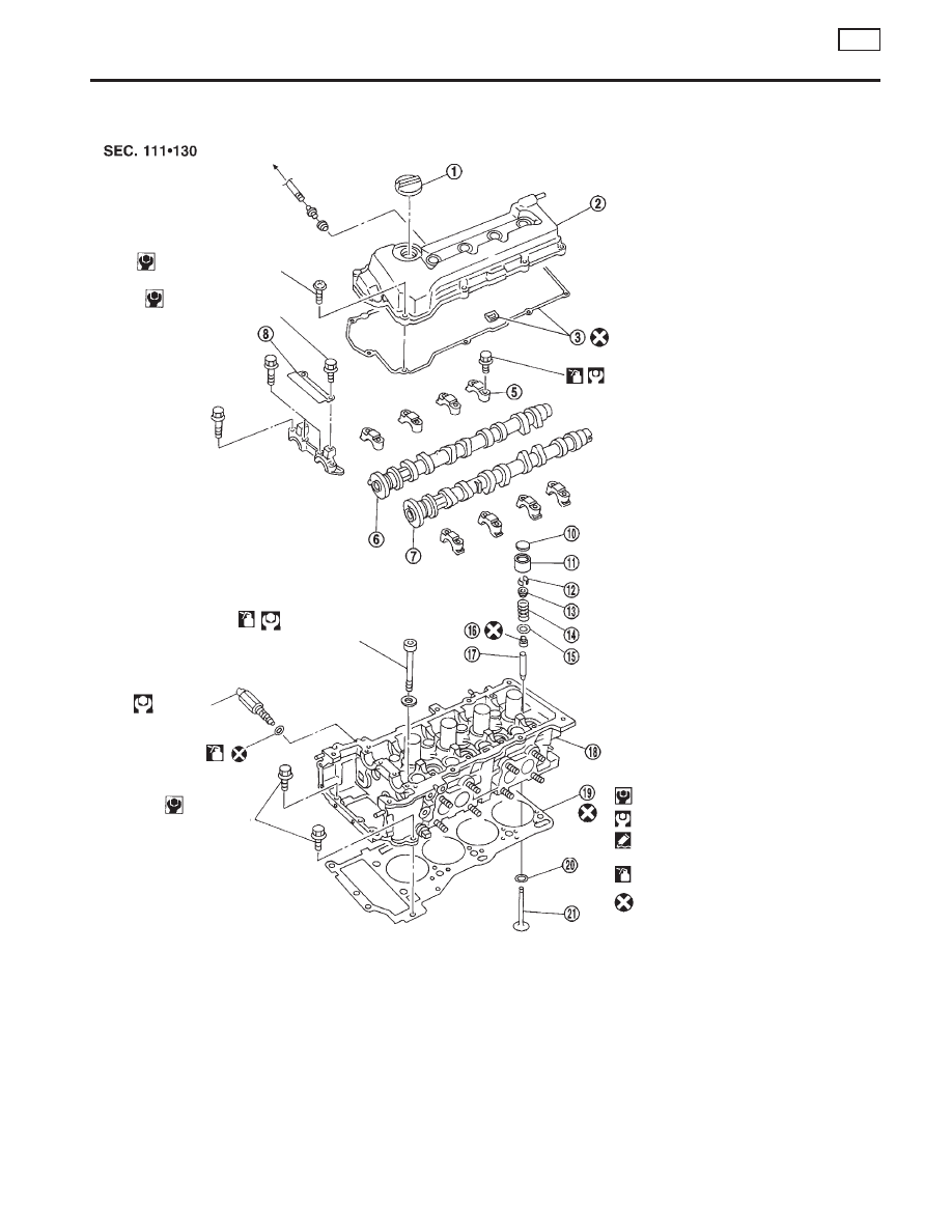
Components
NCEM0016
1.
Oil filler cap
2.
Rocker cover
3.
Rocker cover gasket
4.
VTC solenoid
5.
Camshaft bracket
6.
Intake camshaft
7.
Exhaust camshaft
8.
Timing chain guide
9.
Cylinder head bolt
10. Shim
11. Valve lifter
12. Valve cotter
13. Valve spring retainer
14. Valve spring
15. Valve spring seat
16. Valve oil seal
17. Valve guide
18. Cylinder head
19. Cylinder head gasket
20. Valve seat
21. Valve
SEM913F
To intake manifold
2.0 - 3.9 (0.20 - 0.40, 17.4 - 34.7)
6.3 - 8.3
(0.64 - 0.85, 55.6 - 73.8)
Refer to “Installation” in
“TIMING CHAIN”.
p
9
Refer to “Installation” in
“TIMING CHAIN”.
p
4
24.5 - 34.3
(2.5 - 3.5,
18 - 25)
O-ring
6.3 - 8.3
(0.64 - 0.85,
55.6 - 73.8)
: N·m (kg-m, in-lb)
: N·m (kg-m, ft-lb)
: Use Genuine Liquid Gasket
or equivalent.
: Lubricate with new engine oil.
: Do not re-use.
CYLINDER HEAD
QG
Components
EM-31