Nissan Primera P11. Manual - part 389
1.
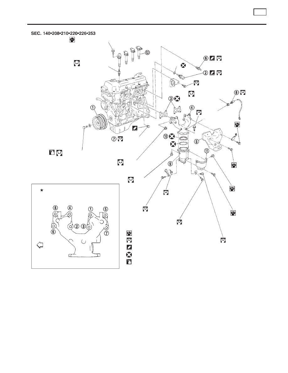
Crankshaft pulley
2.
Engine coolant temperature
3.
Gasket
4.
Exhaust manifold
5.
Exhaust manifold cover
6.
Thermal transmitter
7.
Water drain plug
8.
Heated oxygen sensor
9.
Three way catalyst
10. Converter cap
11. Converter cover
12. Ignition coil
13. Spark plug
SEM866F
5.10 - 6.37 (0.52 - 0.66, 45.1 - 57.3)
p
13
20 - 29
(2.0 - 3.0, 14 - 22)
132 - 152 (13.5 - 15.5, 98 - 112)
34.3 - 44.1
(3.50 - 4.50,
25.3 - 32.5)
★
26 - 29
(2.7 - 3.0,
20 - 22)
6.3 - 8.3
(0.64 - 0.85,
55.6 - 73.8)
6.3 - 8.3
(0.64 - 0.85,
55.6 - 73.8)
6.3 - 8.3
(0.64 - 0.83,
55.6 - 72.0)
6.3 - 8.3
(0.64 - 0.83,
55.6 - 72.0)
Washer
Washer
20 - 26
(2.0 - 2.7, 14 - 20)
20 - 29
(2.0 - 3.0, 14 - 22)
30 - 40
(3.1 - 4.0, 23 - 29)
58.8 - 78.4
(6.0 - 8.0, 43 - 58)
40 - 60
(4.1 - 6.1,
30 - 44)
29 - 34
(3.0 - 3.5,
22 - 25)
29 - 34
(3.0 - 3.5,
22 - 25)
33 - 46
(3.4 - 4.7,
25 - 34)
16 - 21
(1.6 - 2.1,
12 - 15)
33 - 46
(3.4 - 4.7,
25 - 34)
16 - 21
(1.6 - 2.1,
12 - 15)
Exhaust manifold nuts
tightening order
Engine
front
Tighten in
numerical order.
: N·m (kg-m, in-lb)
: N·m (kg-m, ft-lb)
: Use Genuine Liquid Gasket or equivalent.
: Do not re-use.
: Lubricate with new engine oil.
OUTER COMPONENT PARTS
QG
Removal and Installation (Cont’d)
EM-15