Nissan Primera P11. Manual - part 367


  Index      Nissan     Nissan Primera P11 (2001 year) - Service and Repair Manual


Search            


Content   ..  365  366  367  368   ..


Nissan Primera P11. Manual - part 367


DIAGNOSTIC PROCEDURE 1-(3)
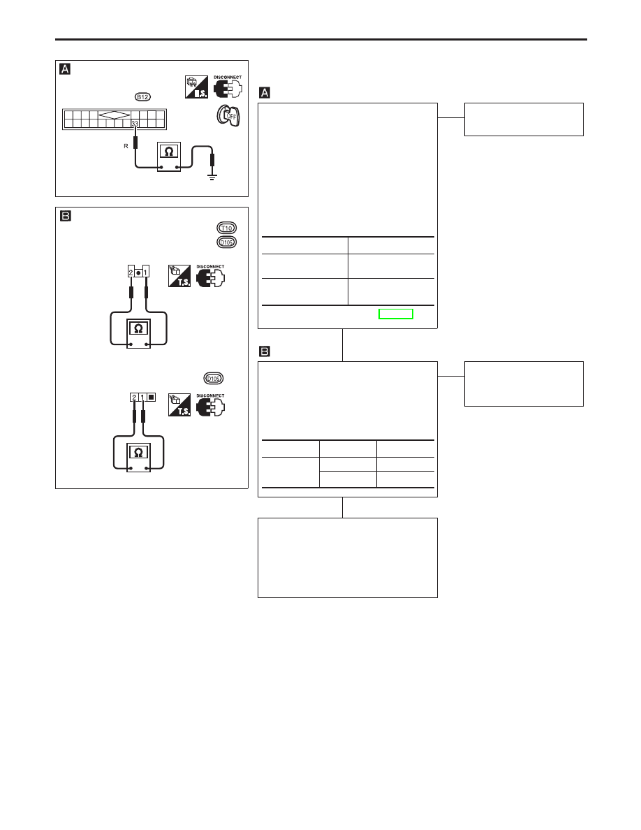
(Trunk room or luggage room lamp switch check)

CHECK TRUNK ROOM OR LUG-
GAGE ROOM LAMP SWITCH INPUT
SIGNAL.
Remove time control unit from fuse
block.
Note: Fuse block (J/B) is very frag-
ile. TCU should be removed care-
fully to avoid breaking the locking
bars.
Check continuity between control unit
terminal

33

and ground.

Refer to wiring diagram in EL-319.

NG

OK

Trunk room or luggage
room lamp switch is OK.

CHECK TRUNK ROOM OR LUG-
GAGE ROOM LAMP SWITCH.
1. Disconnect trunk room or luggage

room lamp switch connector.

2. Check continuity between trunk

room lamp switch terminals.

OK

NG

Replace trunk room or
luggage room lamp
switch.

Check the following.

Trunk room or luggage room lamp
switch ground circuit

Harness for open or short between
control unit and trunk room or lug-
gage room lamp switch

Condition

Continuity

Trunk lid or back

door is open.

Yes

Trunk lid or back

door is closed.

No

Terminals

Condition

Continuity

1

-

2

Closed

No

Open

Yes

YEL459B

Time control
unit connector

YEL460B

Trunk room lamp switch connector

Luggage room lamp switch

Luggage room lamp switch

THEFT WARNING SYSTEM

Trouble Diagnoses (Cont’d)

EL-335

DIAGNOSTIC PROCEDURE 2
(Security indicator check)

CHECK INDICATOR LAMP OUTPUT
SIGNAL.
1) Remove time control unit from fuse

block.
Note: Fuse block (J/B) is very
fragile. TCU should be removed
carefully to avoid breaking the
locking bars.

2) Check voltage between control unit

terminal

18

and ground.

Battery voltage should exist.

Refer to wiring diagram EL-316.

NG

OK

Security indicator lamp is
OK.

Security
indicator on
dashboard

Security indica-
tor built-in com-
bination meter

A

CHECK INDICATOR LAMP.

OK

NG

Replace indicator lamp.

CHECK POWER SUPPLY CIRCUIT
FOR INDICATOR.
1) Disconnect security indicator con-

nector.

2) Check voltage between indicator

terminal

2

and ground.

Battery voltage should exist.

OK

NG

Check the following:

10A fuse [No. 16 ,
located in the fuse
block (J/B)]

Harness for open or
short between security
indicator lamp and
fuse

Check harness for open or short
between security indicator and control
unit.

A

CHECK INDICATOR LAMP.

OK

NG

Replace combination
meter.

CHECK POWER SUPPLY CIRCUIT
FOR INDICATOR.
1) Disconnect combination meter con-

nector.

2) Check voltage between indicator

terminal

23

and ground.

Battery voltage should exist.

OK

NG

Check the following:

10A fuse [No. 16 ,
located in the fuse
block (J/B)]

Harness for open or
short between combi-
nation meter and fuse

Check harness for open or short
between combination meter and con-
trol unit.

YEL461B

Time control
unit connector

YEL462B

Security indicator
connector

YEL037D

THEFT WARNING SYSTEM

Trouble Diagnoses (Cont’d)

EL-336

DIAGNOSTIC PROCEDURE 3
(Door unlock sensor check)

CHECK DOOR UNLOCK SENSOR INPUT
SIGNAL.
Remove time control unit from fuse block.
Note: Fuse block (J/B) is very fragile.
TCU should be removed carefully to
avoid breaking the locking bars.
Check continuity between control unit termi-
nals

25

,

35

,

36

and ground.

Refer to wiring diagram in EL-327.

NG

OK

Door unlock sensor
is OK.

CHECK DOOR UNLOCK SENSOR.
1. Disconnect door unlock sensor connec-

tor.

2. Check continuity between door unlock

sensor terminals.

OK

NG

Replace door
unlock sensor.

Check the following:

Door unlock sensor ground circuit

Harness for open or short between con-
trol unit and door unlock sensor

Terminals

Condition

Continuity

Driver

side door

35

Ground

Locked

No

Unlocked

Yes

Passen-

ger

side door

36

Ground

Locked

No

Unlocked

Yes

Rear

door

25

Ground

Locked

No

Unlocked

Yes

Terminals

Condition

Continuity

2

-

5

Locked

No

Unlocked

Yes

YEL463B

Time control
unit connector

YEL038D

THEFT WARNING SYSTEM

Trouble Diagnoses (Cont’d)

EL-337

DIAGNOSTIC PROCEDURE 4
(Door key cylinder switch check)

CHECK DOOR KEY CYLINDER
SWITCH INPUT SIGNAL (LOCK SIG-
NAL).
Remove time control unit from fuse
block.
Note: Fuse block (J/B) is very fragile.
TCU should be removed carefully to
avoid breaking the locking bars.
Check continuity between time control
unit connector terminal

29

and

ground.

NG

OK

Door key cylinder switch
is OK.

CHECK DOOR KEY CYLINDER
SWITCH.
1) Disconnect door key cylinder switch

connector.

2) Check continuity between door key

cylinder switch terminals.

OK

NG

Replace key cylinder
switch.

Check the following:

Harness connectors

B3

,

M13

Harness connectors

M7

,

D1

Harness connectors

B5

,

D2

Harness connectors

B56

,

D11

Door key cylinder switch ground cir-
cuit

Harness for open or short-circuit
between super lock control unit and
door key cylinder.

Key cylinder switch operation

Continuity

Between neutral and lock

Yes

Unlock/neutral

No

Terminals

Key position

Continuity

1

-

2

Neutral

No

Between

neutral and

lock

Yes

Unlock/

neutral

No

Full stroke

(Lock)

No

YEL447B

Time control unit connector

Continuity exists

Lock

Neutral

Unlock

LH side

Neutral

Unlock

Continuity exists

Lock

RH side

YEL817

Key cylinder switch

Driver side

:

Passenger side:

THEFT WARNING SYSTEM

Trouble Diagnoses (Cont’d)

EL-338


Content   ..  365  366  367  368   ..