Nissan Primera P11. Manual - part 349


  Index      Nissan     Nissan Primera P11 (2001 year) - Service and Repair Manual


Search            


Content   ..  347  348  349  350   ..


Nissan Primera P11. Manual - part 349


DIAGNOSTIC PROCEDURE 5
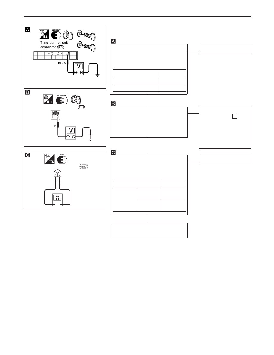
(Key switch check)

CHECK IGNITION KEY SWITCH
INPUT SIGNAL.
Check voltage between control unit ter-
minal

22

and ground.

NG

OK

Key switch is OK.

CHECK KEY SWITCH POWER SUP-
PLY.
Check voltage between key switch har-
ness terminal

2

and ground.

Battery voltage should exist.

OK

NG

Check the following.

10A fuse [No. 16 ,
located in fuse block
(J/B)]

Harness for open or
short between key
switch and fuse

CHECK KEY SWITCH.
1) Disconnect key switch connector.
2) Check continuity between key

switch terminals.

OK

NG

Replace key switch.

Check harness for open or short
between control unit and key switch.

Condition of key switch

Voltage [V]

Key is inserted

Approx. 12

Key withdrawn

0

Terminals

Condition

Continuity

1

-

2

Key is

inserted.

Yes

Key is with-

drawn.

No

YEL034D

YEL826

Key switch connector

YEL827

Key switch connector

POWER DOOR LOCK

Trouble Diagnoses (Cont’d)

EL-263

NOTE

POWER DOOR LOCK

EL-264

Component Parts Location

NEL562

Door key cylinder switch

Lock knob

Time control unit

Door lock actuator assembly

Door lock switch

Time control unit

B11 B12 ,
B96

Door key
cylinder switch
connector

D9

,

D17

Door lock actuator
assembly

D7

,

D16

Door switch

Fuse block (J/B)

POWER DOOR LOCK — Super Lock —

EL-265

System Description/Super Lock for RHD
Models

OUTLINE

Power door lock system with super lock and key reminder is controlled by time control unit. Super lock has
a higher anti-theft performance than conventional power door lock systems.
When super lock is in released condition, lock knob operation locks or unlocks door.
When super lock is in set condition; lock knob operation cannot lock nor unlock door.

OPERATION

Power door lock/unlock and super lock set/release operation by door key cylinder

With the key inserted into front door key cylinder, turning it to LOCK will lock all doors and set super
lock while all doors are closed or any door is open. (Super lock will not be set while key is inserted in
the ignition key cylinder.)

With the key inserted into front door key cylinder, turning it to UNLOCK will unlock all doors and release
super lock.

Power door lock/unlock and super lock set/release operation by multi-remote controller (if equipped)

Pressing multi-remote controller LOCK button will lock all doors and set super lock while all doors are
closed and key is not inserted in the ignition key cylinder.

Pressing once will release super lock and unlock driver’s door.

Pressing twice will release super lock and unlock all doors.

Power door lock and super lock release operation (by NATS IMMU signal)

When the super lock is set, turning ignition key switch to ON will release super lock and unlock all doors.

SEL831U

With super lock released

With super lock set

Door key cylinder

UNLOCK

LOCK

Door lock knob

Door knob rod

Lever B

Lever B

Door lock actuator assembly

Lever A

With super lock set, the connecting

rod is disengaged from lever B.

This enables the linkage to convey

operational force from lever B to lever A.

The door lock knob can still be operated

but this operation does not lock nor

unlock door.

Lever A

Connecting rod

LOCK

UNLOCK

Door lock actuator assembly

POWER DOOR LOCK — Super Lock —

EL-266


Content   ..  347  348  349  350   ..