Nissan Primera P11. Manual - part 295


  Index      Nissan     Nissan Primera P11 (2001 year) - Service and Repair Manual


Search            


Content   ..  293  294  295  296   ..


Nissan Primera P11. Manual - part 295


Removal and Installation

Removal

1. Remove battery negative cable from battery.
2. Remove intake air duct.
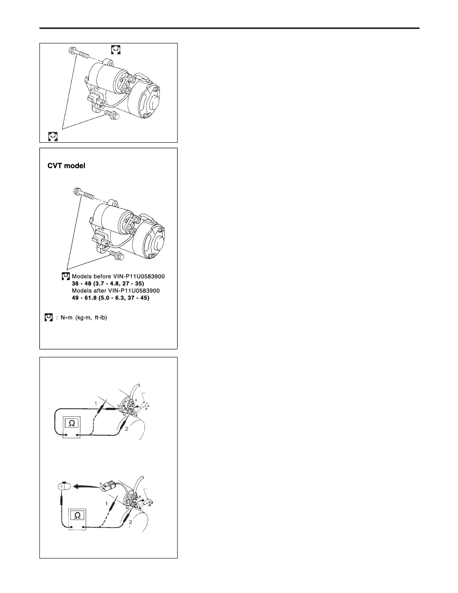
3. Remove starter motor mounting bolts.
4. Remove battery cable from starter motor.
5. Disconnect harness connector from starter motor harness.
6. Remove intake manifold support bracket.
7. Remove starter motor from under the vehicle.

Installation

Installation is reverse order of removal.

Inspection

MAGNETIC SWITCH CHECK

Before starting to check, disconnect battery ground cable.

Disconnect “M” terminal of starter motor.

1. Continuity test (between “S” terminal and switch body).

No continuity ... Replace.

2. Continuity test (between “S” terminal and “M” terminal).

No continuity ... Replace.

NEL301

: N·m (kg-m, ft-lb)

36 - 48 (3.7 - 4.9, 26.6 - 35.4)

YEL947C

NEL302

“M” terminal

“M” terminal

Type 1

Type 2

STARTING SYSTEM

EL-47

PINION/CLUTCH CHECK

1. Inspect pinion teeth.

Replace pinion if teeth are worn or damaged. (Also check
condition of ring gear teeth.)

2. Inspect reduction gear teeth.

Replace reduction gear if teeth are worn or damaged. (Also
check condition of armature shaft gear teeth.)

3. Check to see if pinion locks in one direction and rotates

smoothly in the opposite direction.

If it locks or rotates in both directions, or unusual resistance
is evident. ... Replace.

BRUSH CHECK

Brush cap and lever

Check wear of brush.

Wear limit length:

Refer to SDS (EL-52).

Excessive wear ... Replace.

Brush Spring Pressure

Check brush spring pressure with brush spring detached from
brush.

Spring pressure (with new brush):

Refer to SDS (EL-52).

Not within the specified values ... Replace.

Brush Holder

1. Perform insulation test between brush holder (positive side)

and its base (negative side).

Continuity exists. ... Replace.

2. Check brush to see if it moves smoothly.

If brush holder is damaged or deformed, replace it; clear
sliding surface if dirty.

NEL303

Type 1

Type 2

SEL014Z

Vernier caliper

Brush

SEL015Z

Brush spring

Brush

NEL304

Type 1

STARTING SYSTEM

Inspection (Cont’d)

EL-48

YOKE CHECK

Magnet is secured to yoke by bonding agent. Check magnet to
see that it is secured to yoke and for any cracks. Replace mal-
functioning parts as an assembly.
Holder may move slightly as it is only inserted and not bonded.

CAUTION:

Do not clamp yoke in a vice or strike it with a hammer.

ARMATURE CHECK

1. Continuity test (between two segments side by side).

No continuity ... Replace.

2. Insulation test (between each commutator bar and shaft).

Continuity exists. ... Replace.

3. Check commutator surface.

Rough ... Sand lightly with No. 500 - 600 emery paper.

4. Check diameter of commutator.

Commutator minimum diameter:

Refer to SDS (EL-52).

Less than specified value ... Replace.

SEL018Z

Type 1

Type 2

Magnet

Holder

Magnet

SEL019Z

SEL020Z

Emery paper

SEL021Z

Vernier caliper

Commutator

STARTING SYSTEM

Inspection (Cont’d)

EL-49

M70R
5. Check depth of insulating mica from commutator surface.

Less than 0.3 mm (0.012 in) ... Replace.

S13-305,

S13-531,

S114-800B,

S114-806A,

S114-871,

M2M62071, 0 001 116 006
6. Check depth of insulating mold from commutator surface.

Less than 0.2 mm (0.008 in) ... Undercut to 0.5 to 0.8 mm
(0.020 to 0.031 in)

SEL207P

0,3 mm (0,012 in)

SEL022Z

Round

0.5 - 0.8 mm
(0.020 - 0.031 in)

Correct

File

Commutator

Segment

Mold

Incorrect

STARTING SYSTEM

Inspection (Cont’d)

EL-50


Content   ..  293  294  295  296   ..