Nissan Primera P11. Manual - part 264
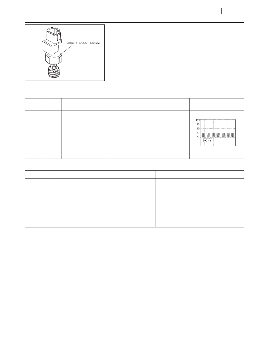
Component Description
NCEC0272
MODELS WITH VEHICLE SPEED SENSOR
The vehicle speed sensor is installed in the transaxle. It contains a
pulse generator which provides a vehicle speed signal to the
speedometer. The speedometer then sends a signal to the ECM.
MODELS WITHOUT VEHICLE SPEED SENSOR
The ABS actuator and electric unit (control unit) provides a vehicle
speed signal to the speedometer. The speedometer then sends a
signal to the ECM.
ECM Terminals and Reference Value
NCEC0273
Specification data are reference values and are measured between each terminal and 48 (ECM ground).
TERMI-
NAL NO.
WIRE
COLOR
ITEM
CONDITION
DATA (DC Voltage)
86
OR/W
Vehicle speed sensor or
ABS actuator and electric
unit (control unit)
[Engine is running]
I
Lift up the vehicle
I
In 2nd gear position
I
Vehicle speed is 40 km/h (25 MPH)
Approximately 2.5V
SEF976W
On Board Diagnosis Logic
NCEC0274
DTC No.
Malfunction is detected when ...
Check Items (Possible Cause)
P0500
0500
I
The almost 0 km/h (0 MPH) signal from vehicle speed
sensor or ABS actuator and electric unit (control unit) is
sent to ECM even when vehicle is being driven.
Models with vehicle speed sensor
I
Harness or connector
(The vehicle speed sensor circuit is open or
shorted.)
I
Vehicle speed sensor
Models without vehicle speed sensor
I
Harness or connector
(The ABS actuator and electric unit (control unit)
is open or shorted.)
I
ABS actuator and electric unit (control unit)
DTC Confirmation Procedure
NCEC0275
CAUTION:
Always drive vehicle at a safe speed.
NOTE:
If “DTC Confirmation Procedure” has been previously conducted,
always turn ignition switch “OFF” and wait at least 9 seconds
before conducting the next test.
TESTING CONDITION:
This procedure may be conducted with the drive wheels lifted
in the shop or by driving the vehicle. If a road test is expected
to be easier, it is unnecessary to lift the vehicle.
SEF080X
DTC P0500 VEHICLE SPEED SENSOR (VSS)
SR20DE
Component Description
EC-255