Index Nissan Nissan Primera P11 (2001 year) - Service and Repair Manual
Search
Content .. 256 257 258 259 ..
Nissan Primera P11. Manual - part 258
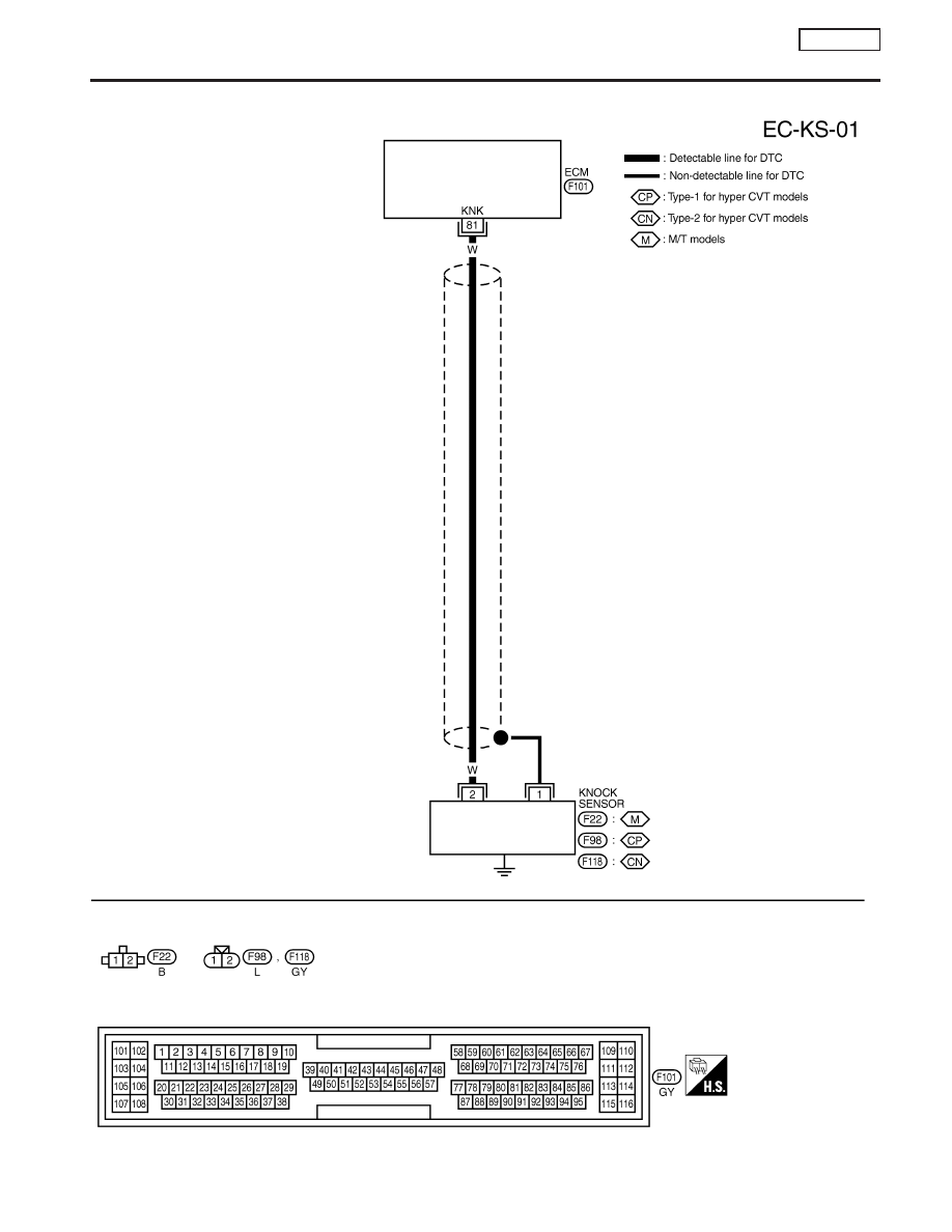
Wiring Diagram
NCEC0210
YEC089A
DTC P0325 KNOCK SENSOR (KS)
SR20DE
EC-231