Nissan Primera P11. Manual - part 255


  Index      Nissan     Nissan Primera P11 (2001 year) - Service and Repair Manual


Search            


Content   ..  253  254  255  256   ..


Nissan Primera P11. Manual - part 255


With GST

Follow the procedure “With CONSULT-II” above.
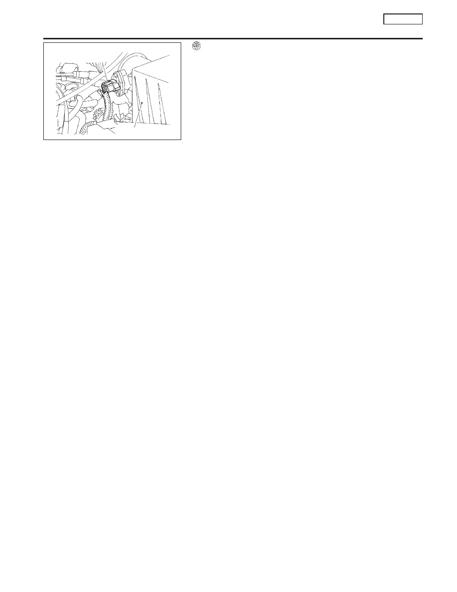
SEF203X

Mass air flow sensor
harness connector

Air cleaner

DTC P0172 FUEL INJECTION SYSTEM FUNCTION

(RICH SIDE)

SR20DE

DTC Confirmation Procedure (Cont’d)

EC-219

Wiring Diagram

NCEC0194

YEC088A

DTC P0172 FUEL INJECTION SYSTEM FUNCTION

(RICH SIDE)

SR20DE

Wiring Diagram

EC-220

Diagnostic Procedure

NCEC0195

1

CHECK FOR EXHAUST AIR LEAK

1. Start engine and run it at idle.
2. Listen for an exhaust air leak before the three way catalyst.

SEF099P

OK or NG

OK

©

GO TO 2.

NG

©

Repair or replace.

2

CHECK HEATED OXYGEN SENSOR 1 (FRONT) CIRCUIT

1. Turn ignition switch “OFF”.
2. Disconnect heated oxygen sensor 1 (front) harness connector and ECM harness connector.

SEF207X

3. Check harness continuity between ECM terminal 62 and heated oxygen sensor 1 (front) harness connector terminal 2.

Refer to wiring diagram.

Continuity should exist.

4. Check harness continuity between ECM terminal 62 (or terminal 2) and ground.

Continuity should not exist.

5. Also check harness for short to ground and short to power.

OK or NG

OK

©

GO TO 3.

NG

©

Repair open circuit or short to ground or short to power in harness or connectors.

3

CHECK FUEL PRESSURE

1. Release fuel pressure to zero.

Refer to EC-SR-31.

2. Install fuel pressure gauge and check fuel pressure.

At idling:

When fuel pressure regulator valve vacuum hose is connected.

Approximately 235 kPa (2.35 bar, 2.4 kg/cm

2

, 34 psi)

When fuel pressure regulator valve vacuum hose is disconnected.

Approximately 294 kPa (2.94 bar, 3.0 kg/cm

2

, 43 psi)

OK or NG

OK

©

GO TO 5.

NG

©

GO TO 4.

Heated oxygen sensor 1
(front) harness connector

Heated oxygen
sensor 1 (front)

DTC P0172 FUEL INJECTION SYSTEM FUNCTION

(RICH SIDE)

SR20DE

Diagnostic Procedure

EC-221

4

DETECT MALFUNCTIONING PART

Check the following.

I

Fuel pump and circuit (Refer to EC-SR-316.)

I

Fuel pressure regulator (Refer to EC-SR-32.)

©

Repair or replace.

5

CHECK MASS AIR FLOW SENSOR

With CONSULT-II

Check “MASS AIR FLOW” in “DATA MONITOR” mode with CONSULT-II.

at idling: 2.5 - 5.0 g

m/sec

at 2,500 rpm: 7.1 - 12.5 g

m/sec

With GST

Check mass air flow sensor signal in MODE 1 with GST.

at idling: 2.5 - 5.0 g

m/sec

at 2,500 rpm: 7.1 - 12.5 g

m/sec

OK or NG

OK

©

GO TO 6.

NG

©

Check connectors for rusted terminals or loose connections in the mass air flow sensor
circuit or engine grounds. Refer to EC-SR-123.

6

CHECK FUNCTION OF INJECTORS

With CONSULT-II

1. Install all parts removed.
2. Start engine.
3. Perform “POWER BALANCE” in “ACTIVE TEST” mode with CONSULT-II.

NEF105A

4. Make sure that each circuit produces a momentary engine speed drop.

Without CONSULT-II

1. Install all parts removed.
2. Start engine.
3. Listen to each injector operating sound.

MEC703B

Clicking noise should be heard.

OK or NG

OK

©

GO TO 7.

NG

©

Perform trouble diagnosis for “INJECTORS”, EC-SR-304.

DTC P0172 FUEL INJECTION SYSTEM FUNCTION

(RICH SIDE)

SR20DE

Diagnostic Procedure (Cont’d)

EC-222


Content   ..  253  254  255  256   ..