Nissan Primera P11. Manual - part 237
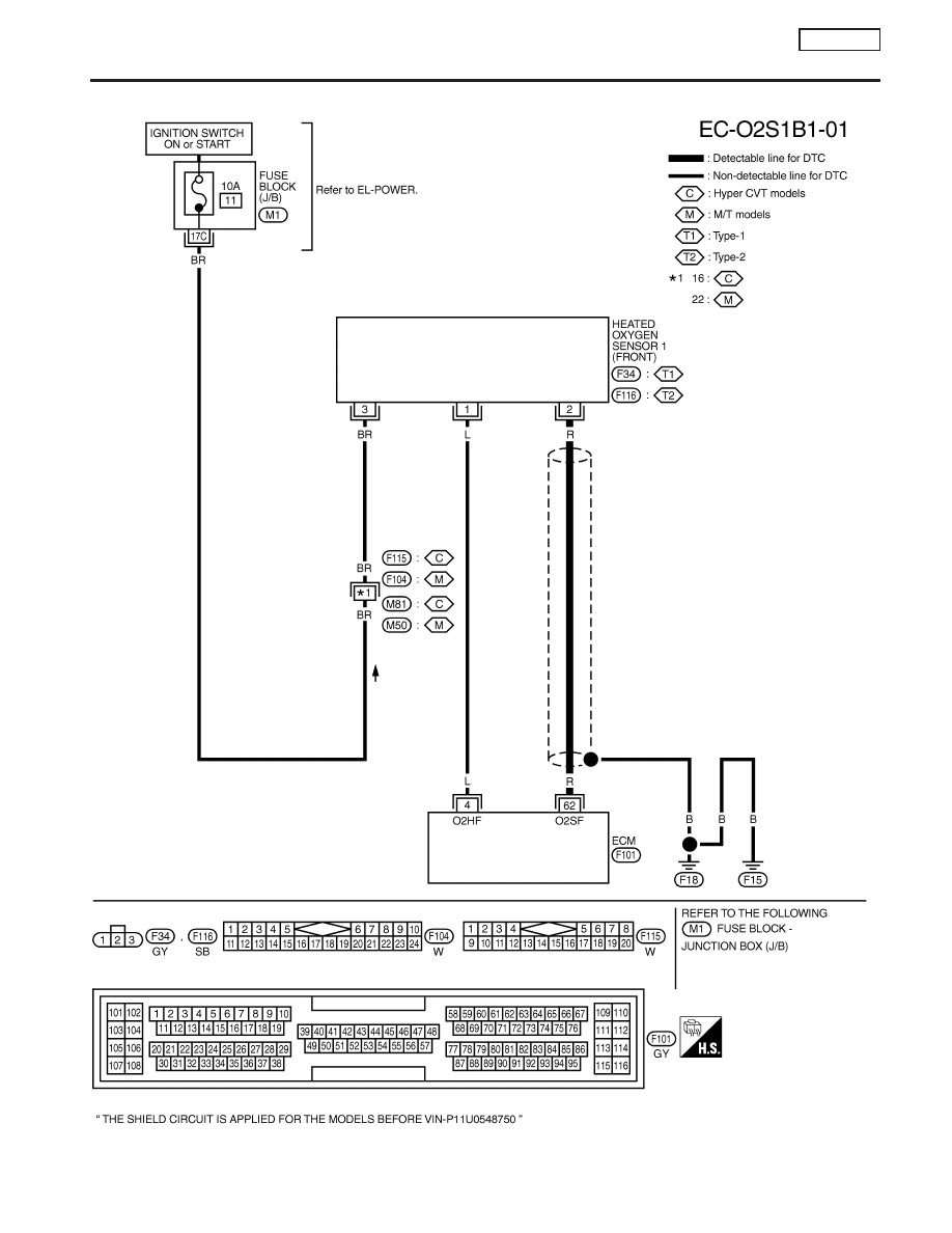
Wiring Diagram
NCEC0100
YEC084A
DTC P0130 HEATED OXYGEN SENSOR 1
(FRONT) (CIRCUIT)
SR20DE
Wiring Diagram
EC-147
|
|
|
Wiring Diagram NCEC0100 YEC084A DTC P0130 HEATED OXYGEN SENSOR 1 (FRONT) (CIRCUIT) SR20DE Wiring Diagram EC-147 |