Nissan Primera P11. Manual - part 128
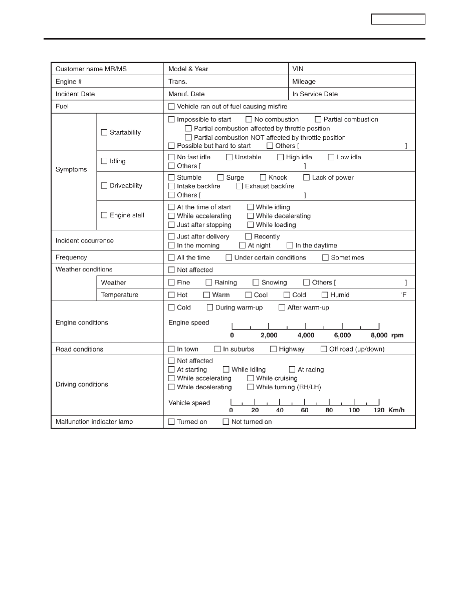
Worksheet Sample
NCEC0036S0101
MTBL0311
TROUBLE DIAGNOSIS — INTRODUCTION
QG16
I
18DE
Introduction (Cont’d)
EC-69
|
|
|
Worksheet Sample NCEC0036S0101 MTBL0311 TROUBLE DIAGNOSIS — INTRODUCTION QG16 I 18DE Introduction (Cont’d) EC-69 |