Nissan Primera P11. Manual - part 117
Fuel Cut Control (at no load & high engine
speed)
DESCRIPTION
NCEC0017
Input/Output Signal Chart
NCEC0017S01
Sensor
Input Signal to ECM
ECM func-
tion
Actuator
Vehicle speed sensor or ABS actuator and
electric unit (control unit)
Vehicle speed
Fuel cut
control
Injectors
PNP switch
Neutral position
Throttle position sensor
Throttle position
Engine coolant temperature sensor
Engine coolant temperature
Crankshaft position sensor (POS)
Engine speed
If the engine speed is above 3,950 rpm with no load, (for example, in Neutral and engine speed over 4,000
rpm) fuel will be cut off after some time. The exact time when the fuel is cut off varies based on engine speed.
Fuel cut will operate until the engine speed reaches 1,150 rpm, then fuel cut is cancelled.
NOTE:
This function is different from deceleration control listed under “Multiport Fuel Injection (MFI) System”,
EC-QG-21.
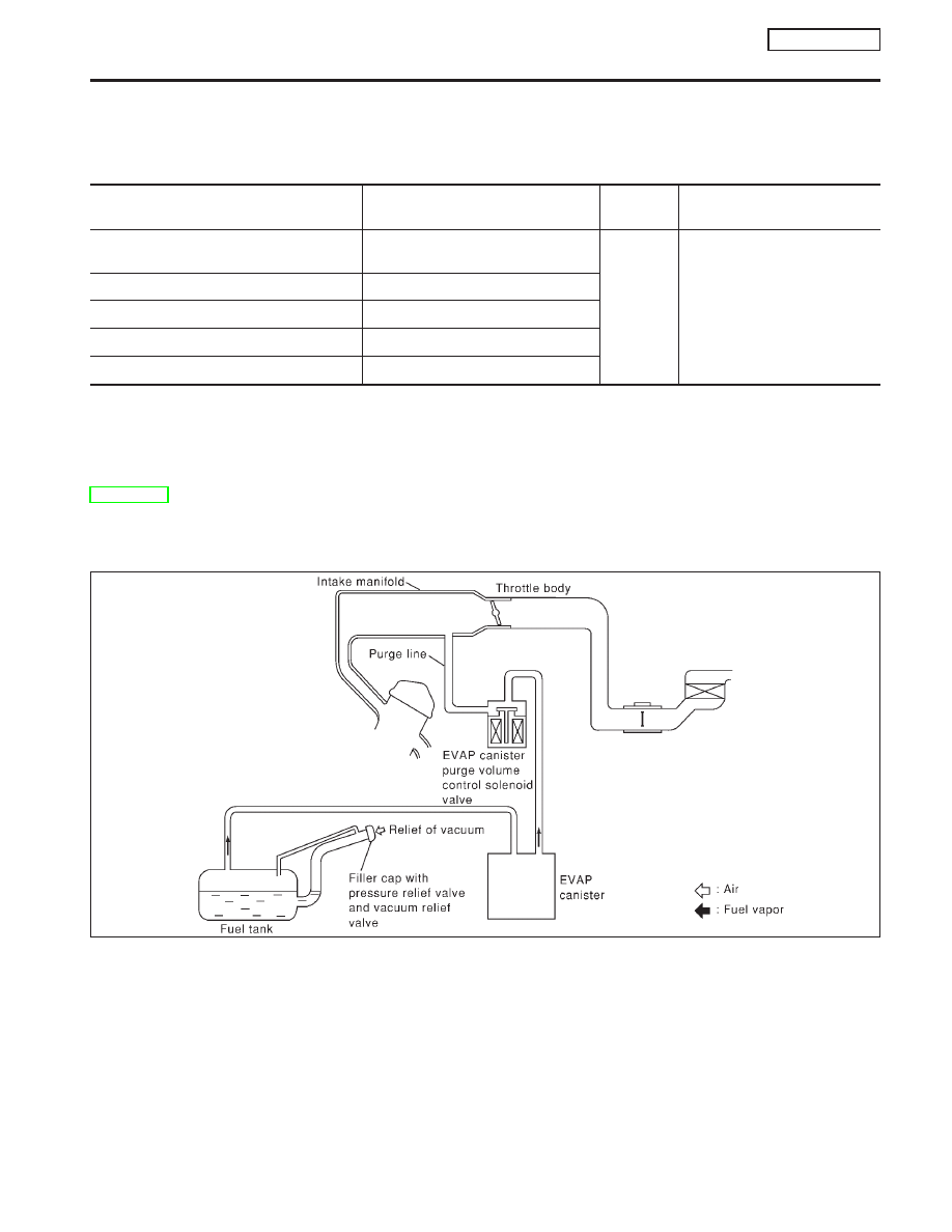
Evaporative Emission System
DESCRIPTION
NCEC0018
The evaporative emission system is used to reduce hydrocarbons emitted into the atmosphere from the fuel
system. This reduction of hydrocarbons is accomplished by activated charcoals in the EVAP canister.
The fuel vapor in the sealed fuel tank is led into the EVAP canister which contains activated carbon and the
vapor is stored there when the engine is not operating or when refueling to the fuel tank.
The vapor in the EVAP canister is purged by the air through the purge line to the intake manifold when the
engine is operating.
EVAP canister purge volume control solenoid valve is controlled by ECM. When the engine operates, the flow
rate of vapor controlled by EVAP canister purge volume control solenoid valve is proportionally regulated as
the air flow increases.
EVAP canister purge volume control solenoid valve also shuts off the vapor purge line during decelerating and
idling.
SEF916WA
ENGINE AND EMISSION BASIC CONTROL
SYSTEM DESCRIPTION
QG16
I
18DE
Fuel Cut Control (at no load & high engine speed)
EC-25