Nissan Primera P11. Manual - part 107


  Index      Nissan     Nissan Primera P11 (2001 year) - Service and Repair Manual


Search            


Content   ..  105  106  107  108   ..


Nissan Primera P11. Manual - part 107


DIAGNOSTIC PROCEDURE

INSPECTION START

EGR CONTROL OPERATION

CHECK OVERALL FUNCTION.
1. Start engine and warm it up suffi-

ciently. (Air conditioner is “OFF”).

2. Perform diagnostic test mode II

(Self-diagnostic results).
Make sure that diagnostic trouble
code No. 55 is displayed.

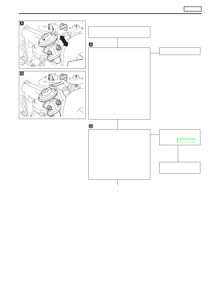
3. Make sure that EGR diaphragm

moves up and down (Use your finger
or a suitable tool) under the following
conditions:

At idle:

Spring does not move.

Racing engine from idle to 2800
rpm:

Spring moves up and down.

NG

E

OK

INSPECTION END

CHECK VACUUM SOURCES TO EGR
VALVE.
1. Disconnect vacuum hoses to EGR

valve.

2. Make sure that vacuum exists under

the following conditions:

At idle:

Vacuum should not exist.

Racing engine from idle to 2800
rpm:

Vacuum should exist.

NG

E

OK

CHECK COMPONENTS
(EGR valve).
(See page EC-CD-135.)

NG

Replace malfunctioning
component(s).

p

A

NEF433

EGR
valve

NEF434

EGR
valve

H

H

H

H

TROUBLE DIAGNOSES 16

CD20T

EGRC-Solenoid Valve (Cont’d)

EC-133

p

A

CHECK CONTROL FUNCTION.

1. Turn ignition switch to “ON”

position.

2. Turn EGRC-solenoid valve A

“ON” and “OFF” in “ACTIVE
TEST” mode with CONSULT-II
and check operating sound.

---------------------------------------------------------------------------------------------------------------------------------------- OR ----------------------------------------------------------------------------------------------------------------------------------------

1. Check voltage between EGRC

solenoid valve A connector ter-
minal

p

1

, and ground with

tester under the following condi-
tions:

Voltage:

At idle

Battery voltage

Engine speed is 2,800 rpm

Approximately 0.4V

NG

E

OK

CHECK VACUUM
HOSE.
Check vacuum hose
for clogging, cracks or
improper connection.

Perform electrical circuit inspection.
Refer to EC-CD-132.

OK

p

B

C2ESA01

NEF435

NEF846

Crack

Clogging

Improper connection

.

NEF436

.

EGRC-solenoid valve
harness connector

H

H

H

TROUBLE DIAGNOSES 16

CD20T

EGRC-Solenoid Valve (Cont’d)

EC-134

COMPONENT INSPECTION

EGR valve

Apply vacuum to EGR vacuum port with a hand vacuum pump.

EGR valve spring should lift.

If NG, replace EGR valve.

EGRC-solenoid valve

Check air passage continuity.

Condition

Air passage

continuity

between

p

A

and

p

B

Air passage

continuity

between

p

A

and

p

C

12V direct current sup-
ply between terminals

p

1

and

p

2

Yes

No

No supply

No

Yes

If NG, replace solenoid valve.

MEF137D

EGR valve

MEC488B

BATTERY

FUSE

TROUBLE DIAGNOSES 16

CD20T

EGRC-Solenoid Valve (Cont’d)

EC-135

Brake Switch

The ECM receives signals from two brake switches. One is a
conventional brake lamp switch, the other is referred to as a
redundant (RDNT) brake switch.
In case the accelerator pedal does not return to the idle position
(pedal sticks), the driver will react by depressing the brake. In
this (emergency) situation, the ECM will disregard the accelera-
tor pedal signal and bring back the engine speed to 1200 rpm.

Malfunction is detected when ...

Check Items

(Possible Cause)

Brake switch circuits are open or shorted.

Harness or connectors
(Brake switch circuits are open or shorted.)

Stop lamp switch

RDNT brake switch

DIAGNOSTIC TROUBLE CONFIRMATION
PROCEDURE

1)

Turn ignition switch to “ON” position and select “DATA
MONITOR” mode with CONSULT-II.

2)

Depress brake pedal for at least 1 minute.

TROUBLE DIAGNOSES 17

CD20T

EC-136


Content   ..  105  106  107  108   ..