Nissan Primera P11. Manual - part 96
YEC805
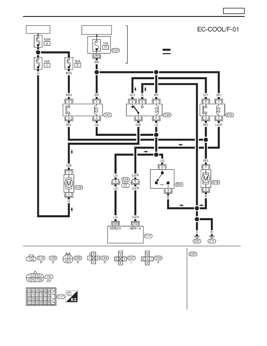
BATTERY
IGNITION SWITCH
ON or START
FUSE
BLOCK
(J/B)
Refer to EL-POWER.
: Detectable line for DTC
: Non-detectable line for DTC
COOLING
FAN
RELAY-3
COOLING
FAN
RELAY-2
COOLING
FAN
RELAY-1
COOLING
FAN
MOTOR-1
LOW
HIGH
TRIPLE-
PRESSURE
SWITCH
COOLING
FAN
MOTOR-2
ECM
REFER TO THE FOLLOWING
FUSE BLOCK - Junction Box (J/B)
TROUBLE DIAGNOSIS 8
CD20T
Cooling Fan (Overheat) (Cont’d)
EC-89