Nissan Primera P11. Manual - part 88


  Index      Nissan     Nissan Primera P11 (2001 year) - Service and Repair Manual


Search            


Content   ..  86  87  88  89   ..


Nissan Primera P11. Manual - part 88


TER-

MINAL

NO.

WIRE

COLOR

ITEM

CONDITION

DATA

(DC Voltage and

Pulse Signal)

403

GY

Air conditioner switch

Engine is running.

Both air conditioner switch and blower
switch are “ON” (Compressor operates)

Approximately 0V

Engine is running.

Air conditioner switch is “OFF”

BATTERY VOLTAGE
(11 - 14V)

405

R/G

Stop lamp switch

Ignition switch “ON”

Brake pedal released

0V

Ignition switch “ON”

Brake pedal depressed

Battery voltage
(11 - 14V)

410

OR

Immobilizer communica-
tion

Ignition switch “ON”

BATTERY VOLTAGE
(4 - 14V)

416

R/B

Brake switch 2

Ignition switch “ON”

Brake pedal released

Battery voltage
(11 -14V)

Ignition switch “ON”

Brake pedal depressed

0V

417

OR/W

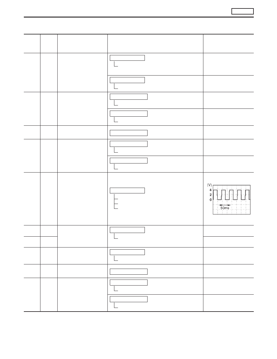
Vehicle speed sensor or
ABS actuator and elec-
tric unit (control unit)

Engine is running.

Lift up the vehicle.
In 2nd gear position
Vehicle speed is 40 km/h (25 mph)

0 - Approximately 4.2V

SEF552S

420

BR/W

Data link connector for
CONSULT-II

Engine is running.

Idle speed (CONSULT-II is connected and
turned on)

Approximately 4 - 9V

415

G/R

Approximately 0V

425

BR

Accelerator position sen-
sor ground

Engine is running.

Idle speed

Approximately 0V

433

LG/W

Accelerator position sen-
sor power supply

Ignition switch “ON”

Approximately 5V

434

W/PU

Accelerator position sen-
sor

Ignition switch “ON”

Accelerator pedal released

0.4 - 0.6V

Ignition switch “ON”

Accelerator pedal fully depressed

Approximately 4.0V

TROUBLE DIAGNOSIS — General Description

CD20T

ECM Terminals and Reference Value (Cont’d)

EC-57

TER-

MINAL

NO.

WIRE

COLOR

ITEM

CONDITION

DATA

(DC Voltage and

Pulse Signal)

435

GY/R

Accelerator position
switch (Idle)

Ignition switch “ON”

Accelerator pedal released

Approximately 0V

Ignition switch “ON”

Accelerator pedal depressed

Approximately 2.7V

442

B/Y

Start signal

Ignition switch “ON”

Approximately 0V

Ignition switch “START”

BATTERY VOLTAGE
(11 - 14V)

439

L/OR

Tachometer

Engine is running. (Warm-up condition)

Idle speed

Approximately 1.1 - 1.5V

SEF550S

Engine is running.

Engine speed is 2,000 rpm

Approximately 1.1 - 1.5V

SEF551S

507

BR/Y

Ignition switch

Ignition switch “LOCK”

0V

Ignition switch “ON”

BATTERY VOLTAGE
(11 - 14V)

TROUBLE DIAGNOSIS — General Description

CD20T

ECM Terminals and Reference Value (Cont’d)

EC-58

Main Power Supply and Ground Circuit

YEC100A

TROUBLE DIAGNOSIS FOR POWER SUPPLY

CD20T

EC-59

INSPECTION START

Start engine.
Is engine running?

Yes

E

No

CHECK POWER SUPPLY-I.
1. Disconnect ECM harness

connector.

2. Turn ignition switch to

“ON” position.

3. Check voltage between

ECM connector terminal

507

and ground

Voltage: Battery voltage

If NG, check the following:

10A fuse

Harness connectors

M52

,

F103

Harness for open or
short-circuit between
ECM and ignition switch.

If NG, replace 10A fuse or
repair harness or connec-
tors.

OK

1. Stop engine.
2. Disconnect ECM harness connector.
3. Turn ignition switch to “ON” position.

F

CHECK POWER SUPPLY-II.
1. Short between ECM connector terminal

325

and engine ground with a jump

wire.

2. Check voltage between ECM terminals

107

,

108

,

109

and ground.

Voltage: Battery voltage

NG

E

OK

Go to

“CHECK

GROUND CIRCUIT” on
page EC-CD-61.

CHECK HARNESS CONTINUITY
BETWEEN ENGINE CONTROL MODULE
RELAY AND ECM
Check harness continuity between ECM
connector terminals

107

,

108

,

109

and

ECM relay connector terminal

p

5

.

Continuity should exist.

If OK, check harness for short.

OK

E

NG

Check the following:

Harness connectors

M89

,

F96

Harness for open or
short-circuit between
ECM relay and ECM.

If NG, repair harness or
connectors.

p

A

NEF863

YEC327

ECM relay

NEF186A

NEF187A

NEF188A

ECM relay
connector

H

H

H

H

H

TROUBLE DIAGNOSIS FOR POWER SUPPLY

CD20T

Main Power Supply and Ground Circuit

(Cont’d)

EC-60


Content   ..  86  87  88  89   ..