Nissan Primera P11. Manual - part 82


  Index      Nissan     Nissan Primera P11 (2001 year) - Service and Repair Manual


Search            


Content   ..  80  81  82  83   ..


Nissan Primera P11. Manual - part 82


Introduction

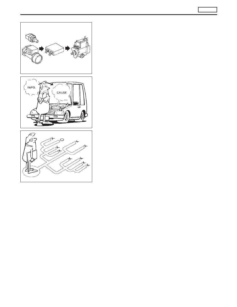
The engine has an ECM to control major systems such as fuel
injection control, fuel injection timing control, glow control
system, etc. The ECM accepts input signals from sensors and
instantly drive the electronic fuel injection pump use the data to
based on current ambient conditions. It is essential that both
input and output signals are correct and stable. At the same time,
it is important that there are no problems such as vacuum leaks,
or other problems with the engine.
It is much more difficult to diagnose a problem that occurs inter-
mittently rather than catastrophically. Most intermittent problems
are caused by poor electric connections or faulty wiring. In this
case, careful checking of suspected circuits may help prevent the
replacement of good parts.
A visual check only may not be sufficient to determine the cause
of the problems. A road test with CONSULT-II or a circuit tester
connected should be performed. Follow the “Work Flow” on the
next page.
Before undertaking actual checks, take a few minutes to talk with
a customer who approaches with a driveability complaint. The
customer can supply good information about such problems,
especially intermittent ones. Find out what symptoms are present
and under what conditions they occur. A “Diagnostic Worksheet”
like the example on next page should be used.
Start your diagnosis by looking for “conventional” problems first.
This will help troubleshoot driveability problems on a vehicle with
an electronically controlled engine.

SEF858S

SEF233G

SEF234G

TROUBLE DIAGNOSIS — Introduction

CD20T

EC-33

Diagnostic Worksheet

There are many operating conditions that lead to the malfunction
of engine components. A good grasp of such conditions can
make troubleshooting faster and more accurate.
In general, each customer feels differently about a problem. It is
important to fully understand the symptoms or conditions for a
customer complaint.
Utilize a diagnostic worksheet like the one shown below in order
to organize all the information for troubleshooting.

WORKSHEET SAMPLE

Customer name

MR/MS

Model & Year

VIN

Engine #

Trans.

Mileage

Incident Date

Manuf. Date

In Service Date

Symptoms

l

Startability

l

Impossible to start

l

No combustion

l

Partial combustion

l

Partial combustion when warming-up engine

l

Partial combustion when cooling down engine

l

Possible but hard to start

l

Others

[

]

l

Idling

l

No fast idle

l

Unstable

l

High idle

l

Low idle

l

Others [

]

l

Driveability

l

Stumble

l

Surge

l

Knock

l

Lack of power

l

Others [

]

l

Engine stall

l

At the time of start

l

While idling

l

While accelerating

l

While decelerating

l

Just after stopping

l

While loading

Incident occurrence

l

Just after delivery

l

Recently

l

In the morning

l

At night

l

In the daytime

Frequency

l

All the time

l

Under certain conditions

l

Sometimes

Weather conditions

l

Not affected

Weather

l

Fine

l

Raining

l

Snowing

l

Others

[

]

Temperature

l

Hot

l

Warm

l

Cool

l

Cold

l

Humid

°F

Engine conditions

l

Cold

l

During warm-up

l

After warm-up

Engine speed

0

2,000

4,000

6,000

8,000 rpm

Road conditions

l

In town

l

In suburbs

l

Highway

l

Off road (up/down)

Driving conditions

l

Not affected

l

At starting

l

While idling

l

At racing

l

While accelerating

l

While cruising

l

While decelerating

l

While turning (RH/LH)

Vehicle speed

0

10

20

30

40

50

60

70

80

90

100 mph

Malfunction indicator

l

Turned on

l

Not turned on

SEF907L

KEY POINTS

WHAT

.....

Vehicle & engine model

WHEN

.....

Date, Frequencies

WHERE .....

Road conditions

HOW

.....

Operating conditions,
Weather conditions,
Symptoms

TROUBLE DIAGNOSIS — Introduction

CD20T

EC-34

Work Flow

CHECK IN

Listen to customer complaints. (Get symptoms.)

..........................................

STEP I

Check, print out or write down, and erase Diagnostic Trouble (malfunction item).

.....................................

STEP II

Symptoms
collected.

No symptoms, except MI
lights up, or Malfunction
Code exists at STEP II.

Verify the symptom by driving in the condition the
customer described.

H

*1

....................................................................................

STEP III

Normal Code
(at STEP II)

Malfunction Code
(at STEP II)

Verify the malfunction item by performing the “DIAGNOSTIC TROUBLE CON-
FIRMATION PROCEDURE”.

*1

.....................................

STEP IV

E

Choose the appropriate action.

Malfunction Code (at STEP II or IV)

Normal Code (at both STEP II and IV)

.....................................

*2

STEP V

BASIC INSPECTION

SYMPTOM BASIS (at STEP I or III)

...........................................................

E

Perform inspections
according to Symptom
Matrix Chart.

H

TROUBLE DIAGNOSIS FOR SPECIFIC MAL-
FUNCTION ITEM.

STEP VI

REPAIR/REPLACE

NG

FINAL CHECK
Confirm that the incident is completely fixed by performing BASIC INSPECTION
and DIAGNOSTIC TROUBLE CONFIRMATION PROCEDURE (or OVERALL
FUNCTION CHECK). Then, erase the unnecessary (already fixed) Malfunction
Item in ECM.

OK

.....................................

STEP VII

CHECK OUT

*1: If the incident cannot be duplicated, refer to GI section (“Incident Simulation Tests”, “HOW TO PERFORM EFFICIENT

DIAGNOSIS FOR AN ELECTRICAL INCIDENT”).

*2: If the on board diagnostic system cannot be performed, check main power supply and ground circuit. Refer to

“TROUBLE DIAGNOSIS FOR MAIN POWER SUPPLY AND GROUND CIRCUIT”, EC-CD-59.

H

H

H

H

H

H

H

H

H

H

H

TROUBLE DIAGNOSIS — Work Flow

CD20T

EC-35

Description for Work Flow

STEP

DESCRIPTION

STEP I

Get detailed information about the conditions and the environment when the incident/symptom occurred
using the “DIAGNOSTIC WORKSHEET” as shown on the previous page.

STEP II

Before confirming the concern, check and write down (print out using CONSULT-II) the malfunction item,
then erase the code. The malfunction item can be used when duplicating the incident at STEP III & IV.
Study the relationship between the cause, specified by malfunction item, and the symptom described by the
customer. (The “Symptom Matrix Chart” will be useful. Refer to EC-CD-47.)

STEP III

Try to confirm the symptom and under what conditions the incident occurs.
The “DIAGNOSTIC WORK SHEET” is useful to verify the incident. Connect CONSULT-II to the vehicle in
DATA MONITOR (AUTO TRIG) mode and check real time diagnosis results.
If the incident cannot be verified, perform INCIDENT SIMULATION TESTS. Refer to GI section.
If the malfunction code is detected, skip STEP IV and perform STEP V.

STEP IV

Try to detect the malfunction item by driving in (or performing) the “DIAGNOSTIC TROUBLE CONFIRMA-
TION PROCEDURE”. Check and read the malfunction item by using CONSULT-II.
During the malfunction item verification, be sure to connect CONSULT-II to the vehicle in DATA MONITOR
(AUTO TRIG) mode and check real time diagnosis results.
If the incident cannot be verified, perform INCIDENT SIMULATION TESTS. Refer to GI section.
In case the “DIAGNOSTIC TROUBLE CONFIRMATION PROCEDURE” is not available, perform the “OVER-
ALL FUNCTION CHECK” instead. The malfunction item cannot be displayed by this check, however, this
simplified “check” is an effective alternative.
The “NG” result of the “OVERALL FUNCTION CHECK” is the same as the DTC detection.

STEP V

Take the appropriate action based on the results of STEP I through IV.
If the malfunction code is indicated, proceed to specific TROUBLE DIAGNOSIS for the malfunction item.
If the normal code is indicated, proceed to the BASIC INSPECTION. Refer to EC-CD-37. Then perform
inspections according to the Symptom Matrix Chart. Refer to EC-CD-47.

STEP VI

Identify where to begin diagnosis based on the relationship study between symptom and possible causes.
Inspect the system for mechanical binding, loose connectors or wiring damage using (tracing) “Harness Lay-
outs”.
Gently shake the related connectors, components or wiring harness with CONSULT-II set in “DATA MONI-
TOR (AUTO TRIG)” mode.
Check the voltage of the related ECM terminals or monitor the output data from the related sensors with
CONSULT-II. Refer to EC-CD-52.
The “DIAGNOSTIC PROCEDURE” in EC section contains a description based on open circuit inspection. A
short circuit inspection is also required for the circuit check in the DIAGNOSTIC PROCEDURE. For details,
refer to GI section (“Circuit Inspection”, “HOW TO PERFORM EFFICIENT DIAGNOSIS FOR AN ELECTRI-
CAL INCIDENT”).
Repair or replace the malfunctioning parts.

STEP VII

Once you have repaired the circuit or replaced a component, you need to run the engine in the same condi-
tions and circumstances which resulted in the customer’s initial complaint.
Perform the “DIAGNOSTIC TROUBLE CONFIRMATION PROCEDURE” and confirm the normal code is
detected. If the incident is still detected in the final check, perform STEP VI by using a different method from
the previous one.
Before returning the vehicle to the customer, be sure to erase the unnecessary (already fixed) malfunction
item in ECM.

TROUBLE DIAGNOSIS — Work Flow

CD20T

EC-36


Content   ..  80  81  82  83   ..