Nissan Frontier D22. Manual - part 904
SC-24
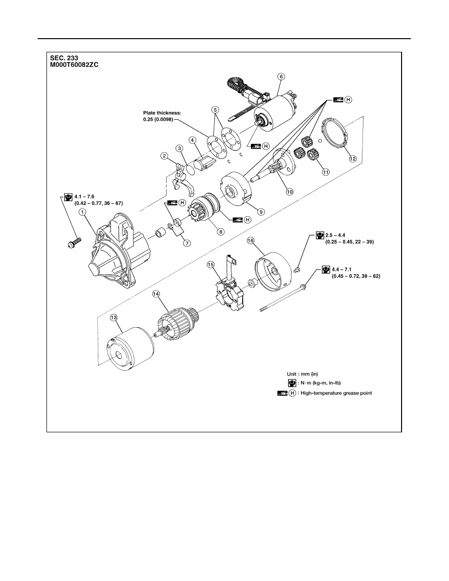
STARTING SYSTEM
VG33E AND VG33ER MODELS
1.
Gear case
2.
Shift lever
3.
Plate
4.
Packing
5.
Adjusting plate
6.
Magnetic switch assembly
7.
Pinion stopper set
8.
Pinion assembly
9.
Internal gear
10. Pinion shaft
11. Planetary gear
12. Packing
13. Yoke
14. Armature
15. Brush holder assembly
16. Rear cover
WKIA1715E