Index Nissan Nissan Frontier D22 Pickup (1998-2004 year) - Service and Repair Manual
Search
Content .. 900 901 902 903 ..
Nissan Frontier D22. Manual - part 902
SC-16
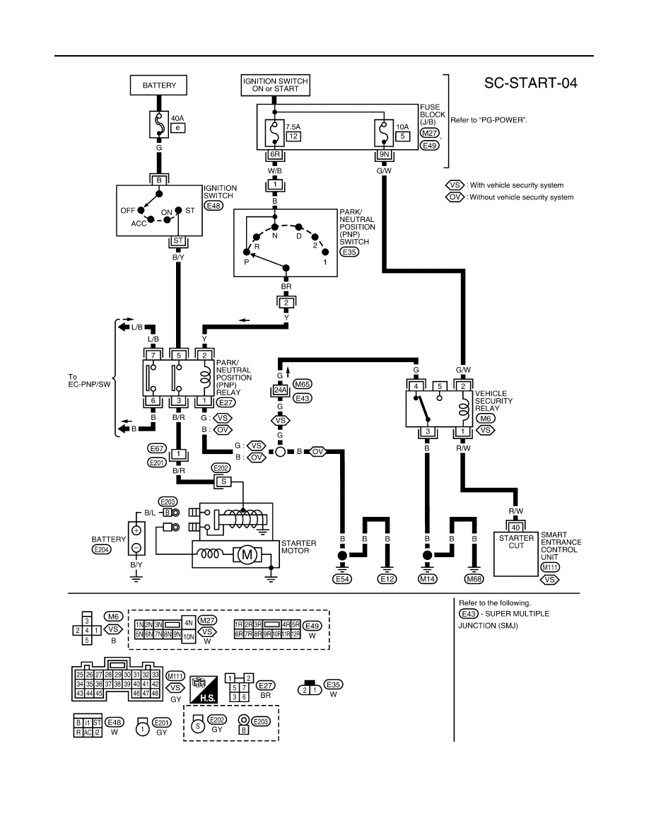
STARTING SYSTEM
VG33E AND VG33ER A/T MODELS
WKWA0957E