Nissan Frontier D22. Manual - part 806
MT-30
[FS5W71C]
GEAR COMPONENTS
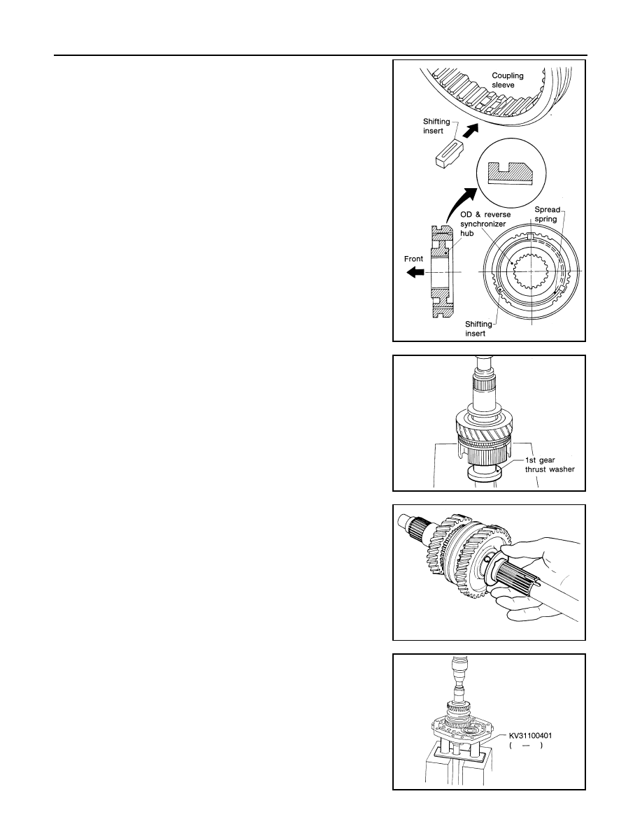
●
Assemble the overdrive and reverse synchronizer.
5.
Assemble front side components to mainshaft.
a.
Install 2nd main gear, 2nd main gear needle bearing and 1st and
2nd synchronizer assembly; then press 1st gear bushing onto
the mainshaft.
b.
Install 1st main gear.
c.
Install steel ball and 1st gear thrust washer.
●
Before installation, apply multi-purpose grease to steel ball
and to both sides of the 1st gear thrust washer.
6.
Install mainshaft and counter gear on adapter plate and main
drive gear on mainshaft as follows:
a.
Press mainshaft assembly into adapter plate using Tool.
SMT207CA
SMT752A
TM358
Tool number
: KV31100401 ( — )
TM439