Nissan Frontier D22. Manual - part 702


  Index      Nissan     Nissan Frontier D22 Pickup (1998-2004 year) - Service and Repair Manual


Search            


Content   ..  700  701  702  703   ..


Nissan Frontier D22. Manual - part 702


CYLINDER HEAD

EM-115

[VG33E and VG33ER]

C

D

E

F

G

H

I

J

K

L

M

A

EM

8.

Use a depth gauge to measure the distance "L" between the
mounting surface of the cylinder head spring seat and the valve
stem end as shown.

If the distance "L" as shown is shorter than specified, repeat
step 5 above to adjust it.

If the distance "L" as shown, is longer and the valve stem tip
cannot be ground within the specified limit to obtain the speci-
fied distance "L", then replace the valve seat with a new one.
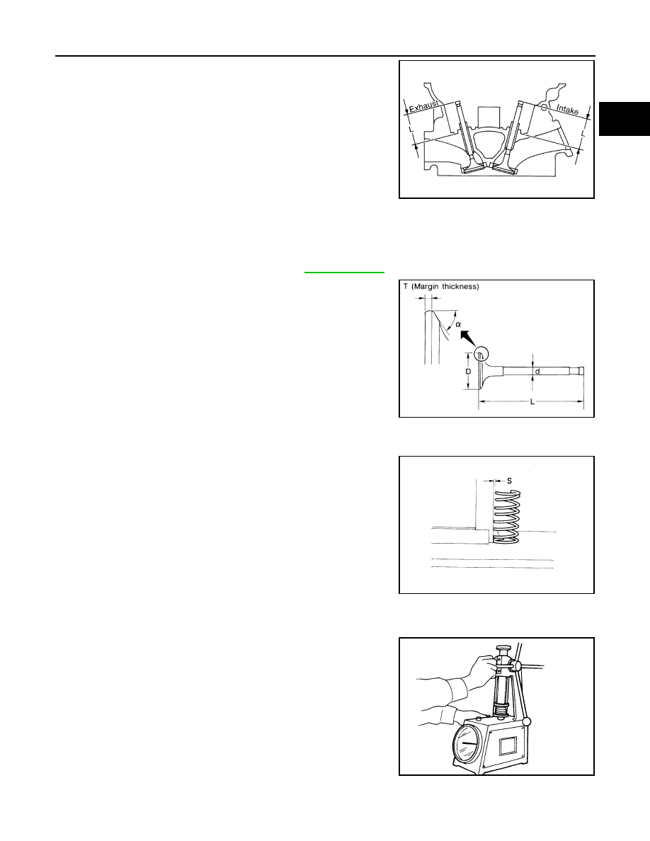
VALVE DIMENSIONS

1.

Check the dimensions of each valve. Refer to 

EM-145, "Valve"

 .

2.

When the valve head has been worn to less then 0.5 mm (0.020
in) in margin thickness "T", replace the valve.

VALVE SPRING
Squareness

1.

Measure the “S” dimension of the valve spring against a right
angle tool for out-of-square as shown.

2.

If the valve spring out-of-square exceeds the limit, replace the valve spring.

Pressure

1.

Check the valve spring pressure at the specified valve open
height as shown.

2.

If not within specification, replace the valve spring.

Intake

: 44.7 - 44.9 mm (1.760 - 1.768 in)

Exhaust

: 45.4 - 45.6 mm (1.787 - 1.795 in)

Valve stem tip grinding allowance

: 0.2 mm (0.008 in) 
or less

SEM621F

SEM188A

Out-of-square

: less than 2.0 mm (0.079 in)

SEM207E

Standard pressure 
with valve open

: 523.7 N (53.4 kg, 117.7 lb) 
at 30.0 mm (1.181 in)

Limit pressure with 
valve open

: 733 N (74.8 kg, 164.8 lb) 
at 30 mm (1.181 in)

EM113

EM-116

[VG33E and VG33ER]

CYLINDER HEAD

ROCKER SHAFT AND ROCKER ARM

1.

Check the rocker shafts for scratches, damage, and wear.

2.

Check the outer diameter of the rocker shaft.

3.

Check the inner diameter of the rocker arm.

CAUTION:

Keep the rocker arm with the hydraulic valve lifter standing
upright to prevent air from entering the hydraulic valve lifter
when checking.

HYDRAULIC VALVE LIFTER

1.

Check the contact and sliding surfaces for wear or scratches.

2.

Check the outer diameter of the valve lifter.

3.

Check the valve lifter guide inner diameter.

Rocker shaft outer diameter

: 17.979 - 18.000 mm 
(0.7078 - 0.7087 in)

SEM761A

Rocker arm inner diameter

: 18.007 - 18.028 mm 
(0.7089 - 0.7098 in)

Rocker arm to shaft clearance

: 0.007 - 0.049 mm 
(0.0003 - 0.0019 in)

SEM762A

Valve lifter outer diameter

: 15.947 - 15.957 mm 
(0.6278 - 0.6282 in)

SEM243E

Valve lifter guide inner diameter

: 16.000 - 16.013 mm 
(0.6299 - 0.6304 in)

Standard clearance between 
valve lifter and lifter guide

: 0.043 - 0.066 mm 
(0.0017 - 0.0026 in)

SEM760A

CYLINDER HEAD

EM-117

[VG33E and VG33ER]

C

D

E

F

G

H

I

J

K

L

M

A

EM

Assembly

EBS00GTP

1.

Install the valve component parts.

Always use a new valve oil seal. Refer to 

EM-99, "VALVE OIL

SEAL"

 .

Install the valve spring (uneven pitch type) with the narrow
pitch side toward cylinder head side.

After installing valve component parts, use plastic hammer to
lightly tap valve stem tip to assure a proper fit.

2.

Install the camshafts, locate plates, and cylinder head rear cov-
ers.

Position the knock pin of the camshaft at the top as shown.

3.

Install the valve lifters and the valve guide.

Assemble the valve lifters in their original position and hold all
of the valve lifters with wire to prevent the lifters from falling
out of the guide.

Remove the wire after installing the lifters and guide.

4.

Install the rocker shafts with the rocker arms.

Tighten the bolts gradually in two or three stages to specifica-
tion in the following camshaft positions:

Before tightening the bolts, the camshaft must be positioned
where the lobe is not contacting the lifter.

a.

Set No. 1 piston at TDC on the compression stroke and tighten
the rocker shaft bolts for No. 2, No. 4 and No. 6 cylinders.

b.

Set No. 4 piston at TDC on the compression stroke and tighten
the rocker shaft bolts for No. 1, No. 3 and No. 5 cylinders.

SEM638B

SEM834B

SEM280A

SEM835BA

EM-118

[VG33E and VG33ER]

CYLINDER HEAD

Installation

EBS00GTQ

1.

Set the No. 1 piston at TDC on the compression stroke as fol-
lows:

a.

Align the crankshaft sprocket aligning mark with the mark on the
oil pump body.

b.

Make sure that the knock pin on camshaft is still positioned at
the top.

2.

Install both cylinder block drain plugs and tighten to specifica-
tion.

Use Genuine High Performance Thread Sealant or equiva-
lent. Refer to 

GI-42, "RECOMMENDED CHEMICAL PROD-

UCTS AND SEALANTS"

 .

3.

Install the exhaust manifolds on to the cylinder head, tighten the
bolts in the numerical order as shown.

CAUTION:

Tighten the exhaust manifold bolts to specification in the
numerical order as shown. Refer to 

EM-80, "OUTER COM-

PONENT PARTS"

 .

SEM836B

Drain plug

: 34 - 44 N·m (3.5 - 4.5 kg-m, 25 - 33 ft-lb)

SEM861CA

SEM862CA

WBIA0193E


Content   ..  700  701  702  703   ..