Nissan Frontier D22. Manual - part 697


  Index      Nissan     Nissan Frontier D22 Pickup (1998-2004 year) - Service and Repair Manual


Search            


Content   ..  695  696  697  698   ..


Nissan Frontier D22. Manual - part 697


TIMING BELT

EM-95

[VG33E and VG33ER]

C

D

E

F

G

H

I

J

K

L

M

A

EM

2.

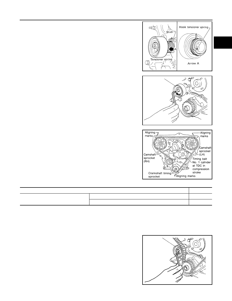
Install the tensioner and tensioner spring.

Once the stud is removed, apply a locking sealant to the
threads of the stud on the cylinder block side before installing.

3.

Turn the tensioner fully outward with a hexagon wrench, and
temporarily tighten the lock nut.

4.

Set the timing belt when the engine is cold.

1. Point the arrow on timing belt toward the front of the belt

cover.

2. Align the white lines on the timing belt with the punchmarks

on the camshaft sprockets and crankshaft sprocket.

Number of timing belt teeth for installation (reference):

5.

Install the remaining parts in the reverse order of removal.

Tension Adjustment

EBS00GTI

AFTER BELT REPLACEMENT

NOTE:
If the timing belt was replaced (or to adjust tension on a used belt), follow this procedure.

1.

Loosen the tensioner lock nut, then turn the tensioner clockwise
and counterclockwise with a hexagon wrench at least two times.

2.

Tighten the tensioner lock nut.

3.

Turn the crankshaft clockwise a full rotation at least two times,
then slowly set the No. 1 piston at TDC on the compression
stroke.

SEM243A

SEM829A

SEM511EA

Total number of timing belt teeth

133

Number of teeth between timing marks

Between LH and RH camshaft sprockets

40

Between LH camshaft sprocket and crankshaft timing sprocket

43

AEM440

EM-96

[VG33E and VG33ER]

TIMING BELT

4.

Measure the deflection of the timing belt midway between the
camshaft sprockets while pushing with the specified force as
shown.

5.

If the belt deflection is not within specification, return to step 1
and repeat the procedure.

AFTER ENGINE OVERHAUL OR ENGINE REASSEMBLY (WITH ROCKER COVERS REMOVED)

NOTE:
If the engine was overhauled or previously disassembled (i.e. intake manifold or cylinder head were removed),
follow this timing belt tension adjustment procedure.

1.

Loosen the rocker shaft bolts to relieve the belt tension caused by the camshafts.

2.

Loosen the tensioner lock nut, keeping the tensioner steady with a hexagon wrench.

3.

Turn the tensioner 70

° to 80° degrees clockwise with a hexagon

wrench to release the belt tension, and temporarily tighten the
lock nut.

4.

Turn the crankshaft clockwise at least twice, then slowly set the
No. 1 piston at TDC on the compression stroke.

5.

Push the middle of the timing belt between the RH camshaft
sprocket and tensioner pulley with the specified force [98 N (10
kg, 22 lb)] to apply tension on part "A" and part "B" of the timing
belt as shown.

6.

Loosen the tensioner lock nut, keeping the tensioner steady with
a hexagon wrench.

7.

Position a feeler gauge size 0.5 mm (0.0206 in) thick and 12.7
mm (0.500 in) wide under the tensioner pulley as shown.

Belt deflection when 
engine is cold (reference 
value)

: 13 - 15 mm (0.51 - 0.59 in) 
at 98 N (10 kg, 22 lb) force

SEM744DA

SEM886B

AEM446

SEM240E

TIMING BELT

EM-97

[VG33E and VG33ER]

C

D

E

F

G

H

I

J

K

L

M

A

EM

8.

Turn the crankshaft clockwise until the feeler gauge is posi-
tioned between the tensioner pulley and the timing belt as
shown.

The timing belt will move about 2.5 teeth.

9.

Tighten the tensioner lock nut, keeping the tensioner steady with
a hexagon wrench.

10. Turn the crankshaft clockwise or counterclockwise to remove

the feeler gauge.

11. Turn the crankshaft clockwise at least two full rotations, then

slowly set the No. 1 piston at TDC on the compression stroke.

12. Measure the deflection of the timing belt midway between the

camshaft sprockets while pushing with a force of 98 N (10 kg, 22
lb) as shown.

13. If the belt deflection is not within specification, return to step 1

and repeat procedure.

SEM889BA

Belt deflection when 
engine is cold (reference 
value)

13 - 15 mm (0.51 - 0.59 in) 
at 98 N (10 kg, 22 lb) force

SEM744DA

EM-98

[VG33E and VG33ER]

TIMING BELT

14. Install the lower and upper belt covers.

15. Install the remaining components in the reverse order of removal.

SEM313F


Content   ..  695  696  697  698   ..