Nissan Frontier D22. Manual - part 688
CYLINDER BLOCK
EM-59
[KA24DE]
C
D
E
F
G
H
I
J
K
L
M
A
EM
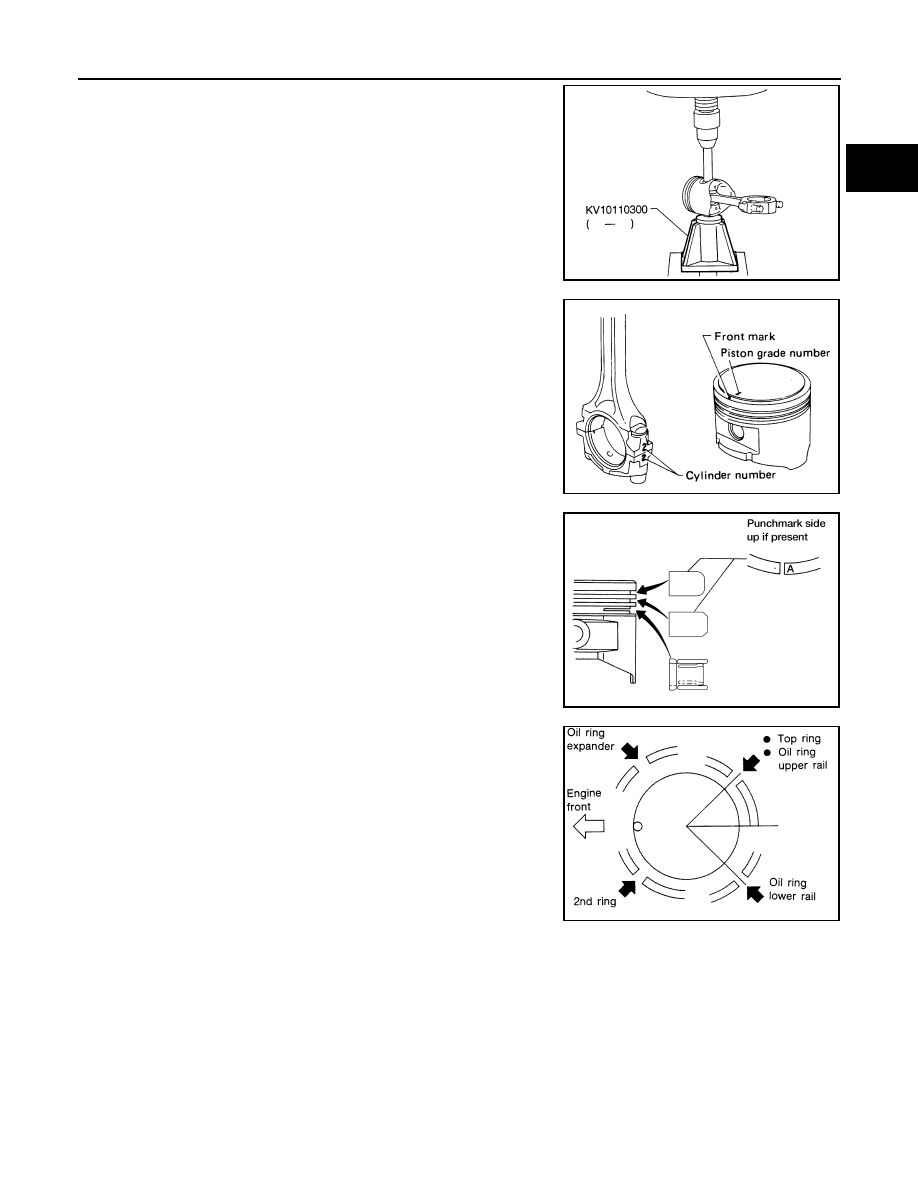
3.
Heat piston to 60
° to 70°C (140° to 158°F) and assemble piston,
piston pin and connecting rod.
●
Align the direction of piston and connecting rod.
●
Numbers stamped on connecting rod and cap correspond to
each cylinder.
●
After assembly, make sure connecting rod swings smoothly.
4.
Set piston rings as shown.
CAUTION:
●
When piston rings are not replaced, make sure that pis-
ton rings are mounted in their original positions.
●
When piston rings are being replaced and no punchmark
is present, piston rings can be mounted with either side
up.
5.
Align piston rings so that end gaps are positioned as shown.
SEM215E
SEM262C
LEM069
SEM160B