Nissan Frontier D22. Manual - part 687


  Index      Nissan     Nissan Frontier D22 Pickup (1998-2004 year) - Service and Repair Manual


Search            


Content   ..  685  686  687  688   ..


Nissan Frontier D22. Manual - part 687


CYLINDER BLOCK

EM-55

[KA24DE]

C

D

E

F

G

H

I

J

K

L

M

A

EM

3.

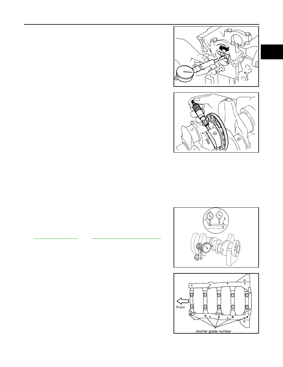
Measure the inner diameter “A” of each main bearing as shown.

4.

Measure the outer diameter “Dm” of each crankshaft main jour-
nal as shown.

5.

Calculate the main bearing clearance.

If the main bearing clearance exceeds the limit, replace the bearing.

6.

If the clearance cannot be adjusted within the standard of any bearing, grind the crankshaft journals and
use an undersized replacement bearing as follows.

a.

When grinding the crankshaft journals, confirm that the “L”
dimension in fillet roll is more than the specified limit.

b.

Grind the crankshaft to use it with replacement parts. Refer to

EM-70, "Crankshaft"

 , and 

EM-71, "Available Main Bearing"

 .

7.

If the crankshaft is reused, measure the main bearing clearance
and select the thickness of the main bearing.
If the crankshaft or cylinder block is replaced, select the thick-
ness of the main bearings as follows.

a.

The grade number of each cylinder block main journal is
punched on the respective cylinder block. These numbers are
punched in either Arabic or Roman numerals.

EEM119

AEM026

Main bearing clearance = A – Dm

Standard

: 0.020 - 0.047 mm (0.0008 - 0.0019 in)

Limit

: 0.1 mm (0.004 in)

“L”

: 0.1 mm (0.004 in)

SEM964

EEM120

EM-56

[KA24DE]

CYLINDER BLOCK

b.

The grade number of each crankshaft main journal is punched
on crankshaft. These numbers are punched in either Arabic or
Roman numerals.

c.

Select the main bearing with a suitable thickness according to the following example and table.
Example:
Main journal grade number is 1or I
Crankshaft journal grade number is 2 or II
Main bearing grade number = 1 + 2 = 3 (Yellow)

Main Bearing Grade Number and Identification Color

Connecting Rod Bearing (Big End)

1.

Install connecting rod bearing to connecting rod and cap.

2.

Install connecting rod cap to connecting rod.

Tighten the connecting rod cap bolts in two stages to specification.

3.

Measure inner diameter “C” of each bearing.

4.

Measure outer diameter “Dp” of each crankshaft pin journal.

SEM272C

Main journal grade number

0

1 or I

2 or II

Crankshaft journal grade 
number

0

0 (Black)

1 (Brown)

2 (Green)

1 or I

1 (Brown)

2 (Green)

3 (Yellow)

2 or II

2 (Green)

3 (Yellow)

4 (Blue)

Connecting rod cap bolts

Stage 1

: 14 - 16 N·m (1.4 - 1.6 kg-m, 10 - 12 ft-lb)

Stage 2

: 60

° - 65° degrees

AEM027

AEM028

CYLINDER BLOCK

EM-57

[KA24DE]

C

D

E

F

G

H

I

J

K

L

M

A

EM

5.

Calculate connecting rod bearing clearance.

If the clearance exceeds the limit, replace the bearing.

6.

If the clearance cannot be adjusted within the standard of any bearing, grind crankshaft journal and use
undersized bearing. Refer to 

EM-71, "UNDERSIZE (SERVICE)"

 .

7.

If the crankshaft is replaced, select the connecting rod bearing
according to the following table.

NOTE:
The grade number of each crankshaft pin are punched on the
crankshaft as shown. These grade numbers are in either Arabic
or Roman numerals.

Method B (using a plastigage)

Measure the bearing clearances using the plastigage.

CAUTION:

Do not turn crankshaft or connecting rod while plastigage
is being inserted.

When bearing clearance exceeds the specified limit, ensure
that the proper bearing has been installed. Then if exces-
sive bearing clearance exists, use a thicker main bearing or
undersized bearing so that the specified bearing clearance
is obtained.

CONNECTING ROD BUSHING CLEARANCE (SMALL END)

1.

Measure inner diameter “C” of bushing.

2.

Measure outer diameter “Dp” of piston pin.

3.

Calculate connecting rod bushing clearance.

If the calculated clearance is out of specification, replace the connecting rod assembly or the piston set
with pin, or both as necessary.

Connecting rod bearing clearance = C 

 Dp

Standard

: 0.010 - 0.035 mm (0.0004 - 0.0014 in)

Limit

: 0.09 mm (0.0035 in)

Crankshaft pin grade number

Connecting rod bearing grade number

0

0

1 or I

1

2 or II

2

SEM567B

EM142

AEM332

Connecting rod bushing clearance = C 

 Dp

Standard

: 0.005 - 0.017 mm (0.0002 - 0.0007 in)

Limit

: 0.023 mm (0.0009 in)

EM-58

[KA24DE]

CYLINDER BLOCK

REPLACEMENT OF CONNECTING ROD BUSHING (SMALL END)

1.

Drive in the small end bushing until it is flush with the rod end
surface.

CAUTION:

Align the oil holes before installing for lubrication.

2.

Ream the bushing until clearance with piston pin is within specification.

FLYWHEEL/DRIVE PLATE RUNOUT

Using a dial gauge, rotate the flywheel/driveplate and measure the
runout by the total dial gauge indicator reading as shown

CAUTION:

Be careful not to damage the ring gear teeth.

Do not allow any magnetic materials to contact the ring
gear teeth.

Do not resurface the flywheel (M/T). Replace as necessary.

Assembly

EBS00GSS

PISTON

1.

Completely remove any foreign material from the cylinder block, inside the crankshaft case, and cylinder
bores by blowing compressed air in the passages and oil passages.

2.

Install the oil jets.

Oil jets for the No. 1 and No. 3 cylinders are a different shape
from those for the No. 2 and No. 4 cylinders, as shown. 

Insert the oil jet knock pin into the cylinder block knock pin
hole, and tighten the knock pin bolt to specification.

SEM062A

Connecting rod bushing clearance

: 0.005 - 0.017 mm (0.0002 - 0.0007 in)

Runout (total indicator 
reading)

: less than 0.15 mm (0.006 in)

AEM100

WBIA0219E

Oil jet bolt

: 30 - 40 N·m (3.1 - 4.1 kg-m, 22 - 30 ft-lb)

PBIC0478E


Content   ..  685  686  687  688   ..