Nissan Frontier D22. Manual - part 546


  Index      Nissan     Nissan Frontier D22 Pickup (1998-2004 year) - Service and Repair Manual


Search            


Content   ..  544  545  546  547   ..


Nissan Frontier D22. Manual - part 546


TROUBLE DIAGNOSIS

EC-1287

[VG33ER]

C

D

E

F

G

H

I

J

K

L

M

A

EC

FUNCTION

INSPECTION PROCEDURE

1.

Turn ignition switch OFF.
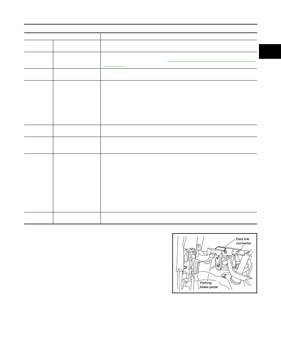
2.

Connect “GST” to data link connector which is located under LH
dash panel near the fuse box cover.

Diagnostic test mode

Function

MODE 1

READINESS TESTS

This mode gains access to current emission-related data values, including analog inputs 
and outputs, digital inputs and outputs, and system status information.

MODE 2

(FREEZE DATA)

This mode gains access to emission-related data value which were stored by ECM during 
the freeze frame. For details, refer to 

EC-1279, "Freeze Frame Data and 1st Trip Freeze 

Frame Data"

 .

MODE 3

DTCs

This mode gains access to emission-related power train trouble codes which were stored 
by ECM.

MODE 4

CLEAR DIAG INFO 

This mode can clear all emission-related diagnostic information. This includes:

Clear number of diagnostic trouble codes (MODE 1)

Clear diagnostic trouble codes (MODE 3)

Clear trouble code for freeze frame data (MODE 1)

Clear freeze frame data (MODE 2)

Reset status of system monitoring test (MODE 1)

Clear on board monitoring test results (MODE 6 and 7)

MODE 6

(ON BOARD TESTS)

This mode accesses the results of on board diagnostic monitoring tests of specific com-
ponents/systems that are not continuously monitored.

MODE 7

(ON BOARD TESTS)

This mode enables the off board test drive to obtain test results for emission-related pow-
ertrain components/systems that are continuously monitored during normal driving condi-
tions.

MODE 8

This mode can close EVAP system in ignition switch ON position (Engine stopped). 
When this mode is performed, EVAP canister vent control valve: Closed, bypass valve: 
Open.
In the following conditions, this mode cannot function.

Low ambient temperature

Low battery voltage

Engine running

Ignition switch OFF

Low fuel temperature

Too much pressure is applied to EVAP system

MODE 9

CALIBRATION ID

This mode is to enable the off-board to request vehicle specific vehicle information such 
as Vehicle Identification Number (VIN) and calibration IDs.

LEC104A

EC-1288

[VG33ER]

TROUBLE DIAGNOSIS

3.

Turn ignition switch ON.

4.

Enter the program according to instruction on the screen or in
the operation manual.

(*: Regarding GST screens in this section, sample screens are
shown.)

5.

Perform each diagnostic mode according to each service proce-
dure.

For further information, see the GST Operation Manual of the
tool maker. 

CONSULT-II Reference Value in Data Monitor Mode

UBS00DSE

Remarks:

● Specification data are reference values.

● Specification data are output/input values which are detected or supplied by the ECM at the connector.

* Specification data may not be directly related to their components signals/values/operations.
i.e. Adjust ignition timing with a timing light before monitoring IGN TIMING, because the monitor may show the specification data in

spite of the ignition timing not being adjusted to the specification data. This IGN TIMING monitors the data calculated by the ECM
according to the signals input from the camshaft position sensor and other ignition timing related sensors.

AEC059B

AEC060B

MONITOR ITEM

CONDITION

SPECIFICATION

ENG SPEED

Run engine and compare CONSULT-II value with the tachometer indica-
tion.

Almost the same speed as the 
tachometer indication.

MAS A/F SE-B1

Engine: After warming up

Air conditioner switch: OFF

Shift lever: N (A/T), Neutral (M/T)

No load 

Idle

1.0 - 1.7V

2,500 rpm

1.7 - 2.3V

COOLAN TEMP/S

Engine: After warming up

More than 70

°C (158°F)

HO2S1 (B1)
HO2S1 (B2)

Engine: After warming up

Maintaining engine speed at 2,000 
rpm.

0 - 0.3V 

←→ Approx. 0.6 - 

1.0V

HO2S1 MNTR (B1)
HO2S1 MNTR (B2)

LEAN 

←→ RICH

Changes more than 5 times 
during 10 seconds.

HO2S2 (B1)
HO2S2 (B2)

Warm-up condition

After keeping engine speed 
between 3,500 and 4,000 rpm for 
1 minute and at idle for 1 minute 
under no load.

Revving engine from idle up to 3,000 
rpm quickly

0 - 0.3V 

←→ Approx. 0.6 - 

1.0V

HO2S2 MNTR (B1)
HO2S2 MNTR (B2)

LEAN 

←→ RICH

VHCL SPEED SE

Turn drive wheels and compare CONSULT-II value speedometer indica-
tion with the speedometer indication.

Almost the same speed as the 
speedometer indication

BATTERY VOLT

Ignition switch: ON (Engine stopped)

11 - 14V

THRTL POS SEN

Engine: After warming up, idle 
the engine

Throttle valve: fully closed

0.15 - 0.85V

Engine: After warming up

 Ignition switch: ON
(Engine stopped)

Throttle valve: fully opened

3.5 - 4.7V

TROUBLE DIAGNOSIS

EC-1289

[VG33ER]

C

D

E

F

G

H

I

J

K

L

M

A

EC

START SIGNAL

Ignition switch: ON 

→ START → ON

OFF 

→ ON → OFF

CLSD THL POS
CLSD THL/P SW

Engine: After warming up, idle 
the engine

Throttle valve: Idle position

ON

Throttle valve: Slightly open

OFF

AIR COND SIG

Engine: After warming up, idle 
the engine

Air conditioner switch: OFF

OFF

Air conditioner switch: ON
(Compressor operates.)

ON

P/N POSI SW 

Ignition switch: ON

Shift lever: P or N (A/T), Neutral (M/T)

ON

Except above

OFF

PW/ST SIGNAL

Engine: After warming up, idle 
the engine

Steering wheel in neutral position
(forward direction)

OFF

The steering wheel is turned

ON

AMB TEMP SW

Ignition switch: ON

Compare ambient air tempera-
ture with the following:

Below 19

°C (66°F)

OFF

Above 25

°C (77°F)

ON

IGNITION SW

Ignition switch: ON 

→ OFF → ON

ON 

→ OFF → ON

INJ PULSE-B1
INJ PULSE-B2

Engine: After warming up

Air conditioner switch: OFF

Shift lever: N (A/T), Neutral (M/T)

No load

Idle

2.4 - 3.7 msec

2,000 rpm 

1.9 - 3.3 msec

B/FUEL SCHDL

Engine: After warming up

Air conditioner switch: OFF

Shift lever: N (A/T), Neutral (M/T)

No load

Idle

1.0 - 1.6 msec

2,000 rpm

0.7 - 1.4 msec

IGN TIMING

Engine: After warming up

Air conditioner switch: OFF

Shift lever: N (A/T), Neutral (M/T)

No load

Idle

10

°±2° BTDC

2,000 rpm

More than 25

° BTDC

IACV-AAC/V

Engine: After warming up

Air conditioner switch: OFF

Shift lever: N (A/T), Neutral (M/T)

No load

Idle

10 - 20%

2,000 rpm

PURG VOL C/V

Engine: After warming up

Air conditioner switch: OFF

Shift lever: N (A/T), Neutral (M/T)

No load

Idle

0%

2,000 rpm

A/F ALPHA-B1
A/F ALPHA-B2

Engine: After warming up

Maintaining engine speed at 2,000 
rpm

54 - 155%

EVAP SYS PRES

Ignition switch: ON

1.8 – 4.8V

AIR COND RLY

Air conditioner switch: OFF 

→ ON

OFF 

→ ON

FUEL PUMP RLY

Ignition switch is turned to ON (Operates for 5 seconds)

Engine running or cranking

ON

Except as shown above

OFF

VENT CONT/V

Ignition switch: ON

OFF

HO2S1 HTR (B1)
HO2S1 HTR (B2)

Engine speed: Below 2,800 rpm

ON

Engine speed: Above 2,800 rpm

OFF

MONITOR ITEM

CONDITION

SPECIFICATION

EC-1290

[VG33ER]

TROUBLE DIAGNOSIS

Major Sensor Reference Graph in Data Monitor Mode

UBS00DSF

The following are the major sensor reference graphs in “DATA MONITOR” mode.

THRTL POS SEN, ABSOL TH·P/S, CLSD THL POS

Below is the data for “THRTL POS SEN”, “ABSOL TH·P/S” and “CLSD THL POS” when depressing the accel-
erator pedal with the ignition switch ON.
The signal of “THRTL POS SEN” and “ABSOL TH·P/S” should rise gradually without any intermittent drop or
rise after “CLSD THL POS” is changed from “ON” to “OFF”.

ENG SPEED, MAS A/F SE-B1, THRTL POS SEN, HO2S2 (B1), HO2S1 (B1), INJ PULSE-B1

Below is the data for “ENG SPEED”, “MAS A/F SE-B1”, “THRTL POS SEN”, “HO2S2 (B1)”, “HO2S1 (B1)” and
“INJ PULSE-B1” when revving engine quickly up to 4,800 rpm under no load after warming up engine suffi-
ciently.

HO2S2 HTR (B1)
HO2S2 HTR (B2)

Engine speed: Below 3,600 rpm after the following conditions are met.

Engine: After warning up

Keeping the engine speed between 3,500 and 4,000 rpm for 1 minute and 
at idle for 1 minute under no load.

ON

Engine speed: Above 3,600 rpm

OFF

SCB/V CON S/V

More than 5 seconds after turning ignition switch ON (Engine stopped)

OFF

Engine speed: Idle

ON

VC/V BYPASS/V

Ignition switch: ON

OFF

CAL/LD VALUE

Engine: After warming up

Air conditioner switch: OFF

Shift lever: N (A/T), Neutral (M/T)

No load

Idle

18.5 - 26.0%

2,500 rpm

18.0 - 21.0%

ABSOL TH·P/S

Engine: After warming up

Ignition switch: ON

More than -40.0 kpa (-300 
mmHg, -11.81 inHg) of vacuum is 
applied to the throttle opener with 
a hand vacuum pump.

Throttle valve: fully closed

0.0%

Engine: After warming up

Ignition switch: ON
(Engine stopped)

Throttle valve: fully opened

Approx. 80%

MASS AIRFLOW

Engine: After warming up

Air conditioner switch: OFF

Shift lever: N (A/T), Neutral (M/T)

No load

Idle

3.3 - 4.8 g·m/s

2,500 rpm

12.0 - 14.9 g·m/s

MONITOR ITEM

CONDITION

SPECIFICATION

SEF306Y


Content   ..  544  545  546  547   ..