Nissan Frontier D22. Manual - part 488
DTC P1400 EGRC-SOLENOID VALVE
EC-1055
[VG33E]
C
D
E
F
G
H
I
J
K
L
M
A
EC
Specification data are reference values and are measured between each terminal and ground.
CAUTION:
Do not use ECM ground terminals when measuring input/output voltage. Doing so may result in dam-
age to the ECM's transistor. Use a ground other than ECM terminals, such as the ground.
Diagnostic Procedure
UBS00DOC
1.
CHECK EGRC-SOLENOID VALVE
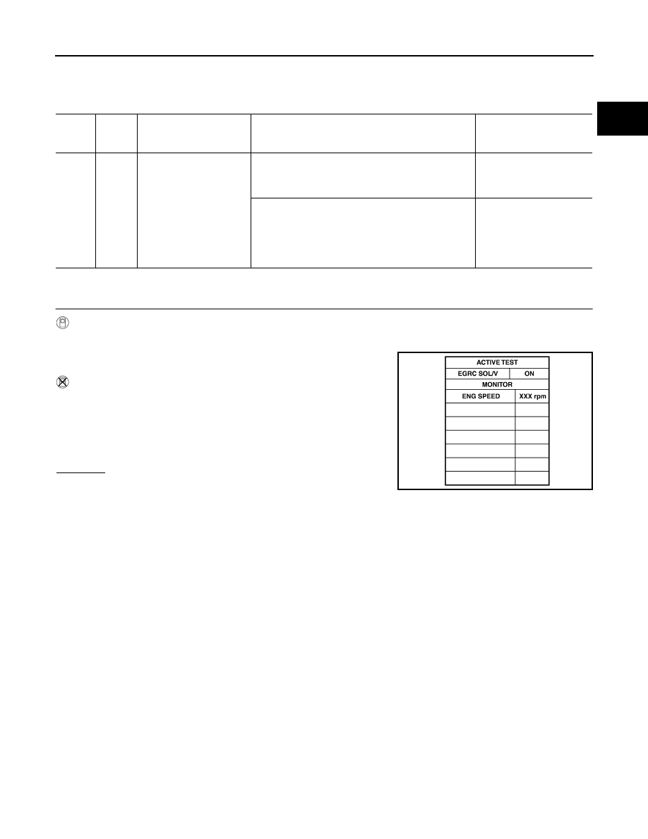
With CONSULT-II
1.
Turn ignition switch ON.
2.
Turn EGRC-solenoid valve “ON” and “OFF” in “ACTIVE TEST”
mode with CONSULT-II and check operating sound.
Without CONSULT-II
1.
Start engine and rev engine up to 3,000 rpm quickly.
2.
When disconnecting and reconnecting the EGRC-solenoid valve
harness connector, make sure that the EGRC-solenoid valve
makes operating sound. (The DTC or the 1st trip DTC for the
EGRC-solenoid valve will be displayed, however, ignore it.)
OK or NG
OK (With CONSULT-II)>>GO TO 6.
OK (Without CONSULT-II)>>GO TO 7.
NG
>> GO TO 2
TER-
MINAL
NO.
WIRE
COLOR
ITEM
CONDITION
DATA (DC Voltage)
103
G/W
EGRC-solenoid valve
[Engine is running]
●
Warm-up condition
●
Idle speed
BATTERY VOLTAGE
(11 - 14V)
[Engine is running]
●
Warm-up condition
●
M/T models: Lift up drive wheels and shift to 1st
gear position
●
Revving engine from idle up to 3,000 rpm quickly
0 - 1V
SEF722Z