Nissan Frontier D22. Manual - part 471


  Index      Nissan     Nissan Frontier D22 Pickup (1998-2004 year) - Service and Repair Manual


Search            


Content   ..  469  470  471  472   ..


Nissan Frontier D22. Manual - part 471


DTC P0505 ISC SYSTEM

EC-987

[VG33E]

C

D

E

F

G

H

I

J

K

L

M

A

EC

3.

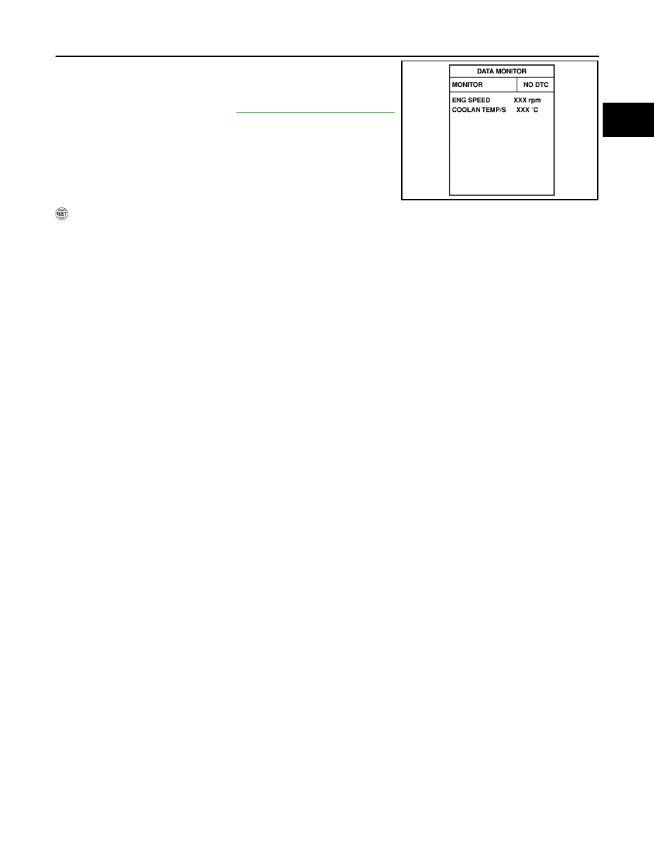
Turn ignition switch ON again and select “DATA MONITOR”
mode with CONSULT-II.

4.

Start engine and run it for at least 1 minute at idle speed.

5.

If 1st trip DTC is detected, go to 

EC-989, "Diagnostic Procedure"

.

 With GST

Follow the procedure “With CONSULT-II”.

SEF174Y

EC-988

[VG33E]

DTC P0505 ISC SYSTEM

Wiring Diagram

UBS00DMG

BBWA1091E

DTC P0505 ISC SYSTEM

EC-989

[VG33E]

C

D

E

F

G

H

I

J

K

L

M

A

EC

Specification data are reference values and are measured between each terminal and ground.

CAUTION:

Do not use ECM ground terminals when measuring input/output voltage. Doing so may result in dam-
age to the ECM's transistor. Use a ground other than the ECM terminals, such as the ground.

: Average voltage for pulse signal (Actual pulse signal can be confirmed by oscilloscope.)

Diagnostic Procedure

UBS00DMH

1. 

CHECK IACV-AAC VALVE POWER SUPPLY CIRCUIT

1.

Stop engine.

2.

Disconnect IACV-AAC valve harness connector.

3.

Turn ignition switch ON.

4.

Check voltage between terminal 2 and ground with CONSULT-II
or tester.

OK or NG

OK

>> GO TO 3.

NG

>> GO TO 2.

TER-

MINAL 

NO.

WIRE 

COLOR

ITEM

CONDITION

DATA (DC Voltage)

101

OR/L

IACV-AAC valve

[Engine is running]

Warm-up condition

Idle speed

NOTE:
The pulse cycle changes depending on rpm 
at idle

8 - 11V

[Engine is running]

Warm-up condition

Engine speed is 3,000 rpm

7 - 10V

SEF005V

SEF692W

BBIA0427E

Voltage: Battery voltage

SEF651W

EC-990

[VG33E]

DTC P0505 ISC SYSTEM

2. 

DETECT MALFUNCTIONING PART

Check the following.

Harness connectors M81, F36

Harness connectors F37, F101

Fuse block (J/B) connector M27

10A fuse

Harness for open or short between IACV-AAC valve and fuse

>> Repair open circuit or short to ground or short to power in harness or connectors.

3. 

CHECK IACV-AAC VALVE OUTPUT SIGNAL CIRCUIT FOR OPEN AND SHORT

1.

Turn ignition switch OFF.

2.

Disconnect ECM harness connector.

3.

 Check harness continuity between ECM terminal 101 and IACV-AAC valve terminal 1.
Refer to Wiring Diagram.

4.

Also check harness for short to ground and short to power.

OK or NG

OK

>> GO TO 5.

NG

>> GO TO 4.

4. 

DETECT MALFUNCTIONING PART

Check the following.

Harness connectors F101, F37

Harness for open or short between IACV-AAC valve and ECM

>> Repair open circuit or short to ground or short to power in harness or connectors.

5. 

CHECK IACV-AAC VALVE

1.

Disconnect IACV-AAC valve harness connector.

2.

Remove IACV-AAC valve.

Check IACV-AAC valve resistance.

Check plunger for seizing or sticking.

Check for broken spring.

3.

Supply battery voltage between IACV-AAC valve connector ter-
minals.
Plunger should move.

OK or NG

OK

>> GO TO 6.

NG

>> Replace IACV-AAC valve.

6. 

CHECK INTERMITTENT INCIDENT

Refer to 

EC-696, "TROUBLE DIAGNOSIS FOR INTERMITTENT INCIDENT"

 .

>> INSPECTION END.

Continuity should exist.

Resistance: Approximately 10

 [at 20°C (68°F)]

SEF202V


Content   ..  469  470  471  472   ..