Nissan Frontier D22. Manual - part 468
DTC P0461 FUEL LEVEL SENSOR
EC-975
[VG33E]
C
D
E
F
G
H
I
J
K
L
M
A
EC
WITH GST
NOTE:
Start from step 8, if it is possible to confirm that the fuel cannot be drained by 30 (7-7/8 US gal, 6-5/8
Imp gal) in advance.
1.
Prepare a fuel container and a spare hose.
2.
Release fuel pressure from fuel line, refer to
EC-616, "FUEL PRESSURE RELEASE"
3.
Remove the fuel feed hose on the fuel level sensor unit.
4.
Connect a spare fuel hose where the fuel feed hose was removed.
5.
Turn ignition switch OFF.
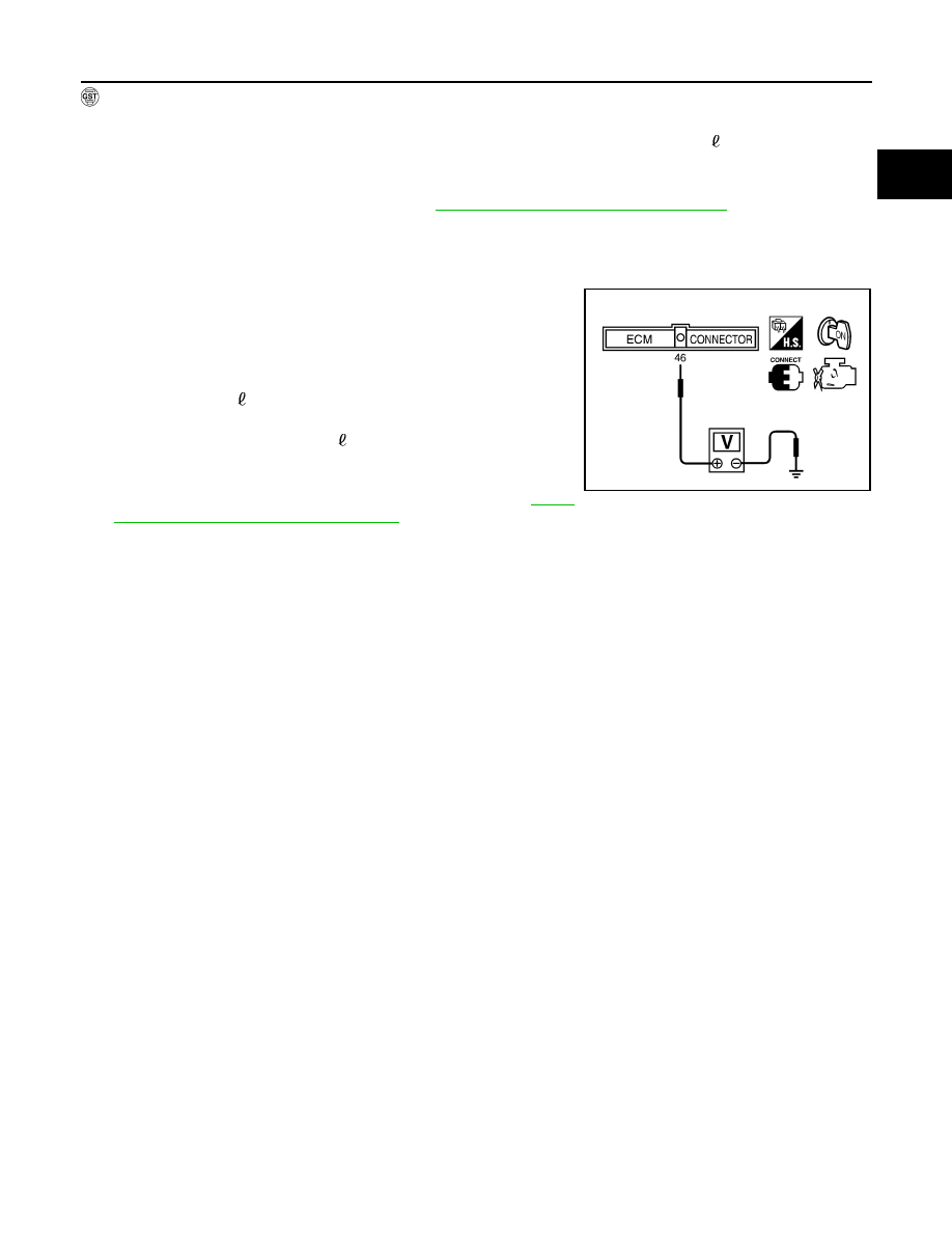
6.
Set voltmeters probe between ECM terminal 46 (fuel level sen-
sor signal) and ground.
7.
Turn ignition switch ON.
8.
Check voltage between ECM terminal 46 and ground and note
it.
9.
Drain fuel by 30 (7-7/8 US gal, 6-5/8 Imp gal) from the fuel
tank using proper equipment.
10. Fill fuel into the fuel tank for 30 (7-7/8 US gal, 6-5/8 Imp gal).
11. Confirm that the voltage between ECM terminal 46 and ground
changes more than 0.03V during step 8 - 10.
If NG, check component of fuel level sensor, refer to
"FUEL LEVEL SENSOR UNIT CHECK"
SEF802Z