Nissan Frontier D22. Manual - part 457


  Index      Nissan     Nissan Frontier D22 Pickup (1998-2004 year) - Service and Repair Manual


Search            


Content   ..  455  456  457  458   ..


Nissan Frontier D22. Manual - part 457


DTC P0447 EVAP CANISTER VENT CONTROL VALVE

EC-931

[VG33E]

C

D

E

F

G

H

I

J

K

L

M

A

EC

Specification data are reference values and are measured between each terminal and ground.

CAUTION:

Do not use ECM ground terminals when measuring input/output voltage. Doing so may result in dam-
age to the ECM's transistor. Use a ground other than the ECM terminals, such as the ground.

 Diagnostic Procedure

UBS00DL7

1. 

INSPECTION START

Do you have CONSULT-II?

Yes or No

Yes

>> GO TO 2.

No

>> GO TO 3.

2. 

CHECK EVAP CANISTER VENT CONTROL VALVE CIRCUIT

 With CONSULT-II

1.

Turn ignition switch OFF and then turn ON.

2.

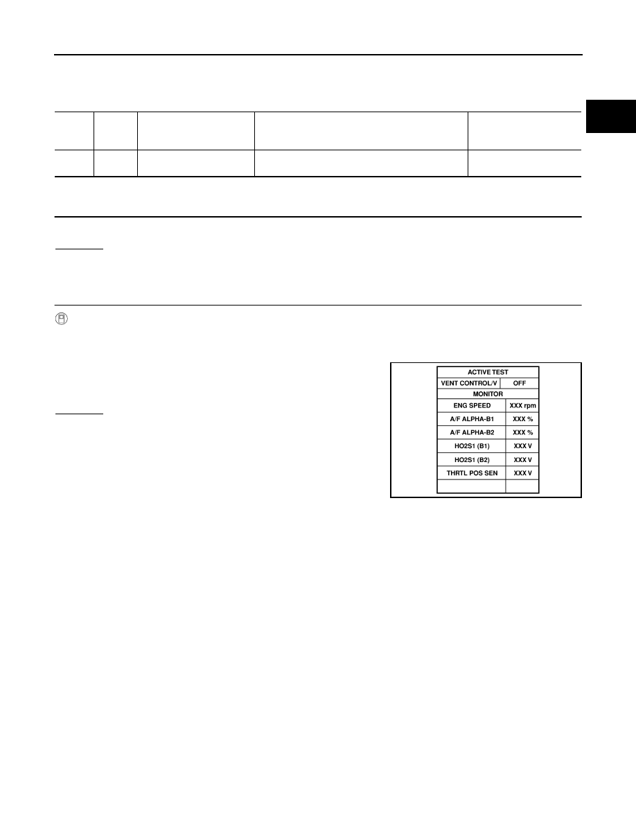
Select “VENT CONTROL/V” in “ACTIVE TEST” mode with CONSULT-II.

3.

Touch “ON/OFF” on CONSULT-II screen.

4.

 Check for operating sound of the valve.
Clicking noise should be heard.

OK or NG

OK

>> GO TO 7.

NG

>> GO TO 3.

TER-

MINAL 

NO.

WIRE 

COLOR

ITEM

CONDITION

DATA (DC Voltage)

108

R/G

EVAP canister vent control 
valve

[Ignition switch: ON]

BATTERY VOLTAGE
(11 - 14V)

SEF989Y

EC-932

[VG33E]

DTC P0447 EVAP CANISTER VENT CONTROL VALVE

3. 

CHECK EVAP CANISTER VENT CONTROL VALVE POWER SUPPLY CIRCUIT

1.

Turn ignition switch OFF.

2.

Disconnect EVAP canister vent control valve harness connector.

3.

Turn ignition switch ON.

4.

Check voltage between terminal 1 and ground with CONSULT-II
or tester.

OK or NG

OK

>> GO TO 5.

NG

>> GO TO 4.

4. 

DETECT MALFUNCTIONING PART

Check the following.

Harness connectors E43, M65 

Harness connectors M67, C1

Fuse block (J/B) connector E49

10A fuse

Harness for open or short between EVAP canister vent control valve and fuse

>> Repair harness or connectors.

5. 

CHECK EVAP CANISTER VENT CONTROL VALVE OUTPUT SIGNAL CIRCUIT FOR OPEN AND 

SHORT

1.

Turn ignition switch OFF.

2.

Disconnect ECM harness connector.

3.

Check harness continuity between ECM terminal 108 and EVAP canister vent control valve terminal 2.
Refer to Wiring Diagram.

4.

Also check harness for short to ground and short to power.

OK or NG

OK

>> GO TO 7.

NG

>> GO TO 6.

SEF143S

Voltage: Battery voltage

SEF648W

Continuity should exist.

DTC P0447 EVAP CANISTER VENT CONTROL VALVE

EC-933

[VG33E]

C

D

E

F

G

H

I

J

K

L

M

A

EC

6. 

DETECT MALFUNCTIONING PART

Check the following.

Harness connectors C1, M67

Harness connectors M81, F36

Harness for open or short between EVAP canister vent control valve and ECM

>> Repair open circuit or short to ground or short to power in harness or connectors.

7. 

CHECK EVAP CANISTER VENT CONTROL VALVE

 With CONSULT-II

1.

Perform “VENT CONTROL/V” in “ACTIVE TEST” mode.

2.

Check air passage continuity and operation delay time.

Operation takes less than 1 second.

 Without CONSULT-II

1.

Check air passage continuity and operation delay time under the
following conditions.

Operation takes less than 1 second.
If NG or operation takes more than 1 second, clean valve using
air blower or replace as necessary.
If portion B  is rusted, replace control valve.
Make sure new O-ring is installed properly.

OK or NG

OK

>> GO TO 8.

NG

>> Replace EVAP canister vent control valve.

8. 

CHECK INTERMITTENT INCIDENT

Refer to 

EC-696, "TROUBLE DIAGNOSIS FOR INTERMITTENT INCIDENT"

 .

>> INSPECTION END.

Condition

VENT CONTROL/V

Air passage continuity between 

A and B

ON

No

OFF

Yes

SEF013Z

Condition

Air passage continuity 

between A and B

12V direct current supply between 
terminals 1 and 2

No

OFF

Yes

BBIA0309E

EC-934

[VG33E]

DTC P0452 EVAP CONTROL SYSTEM PRESSURE SENSOR

DTC P0452 EVAP CONTROL SYSTEM PRESSURE SENSOR

PFP:25085

Component Description

UBS00DL8

The EVAP control system pressure sensor detects pressure in the
purge line. The sensor output voltage to the ECM increases as pres-
sure increases. The EVAP control system pressure sensor is not
used to control the engine system. It is used only for on board diag-
nosis.

CONSULT-II Reference Value in Data Monitor Mode

UBS00DL9

Specification data are reference values.

On Board Diagnosis Logic

UBS00DLA

DTC Confirmation Procedure

UBS00DLB

NOTE:
If DTC Confirmation Procedure has been previously conducted, always turn ignition switch OFF and wait at
least 5 seconds before conducting the next test.
TESTING CONDITION:
Always perform test at a temperature of 5

°C (41°F) or more.

 WITH CONSULT-II

1.

Start engine and warm it up to normal operating temperature.

2.

Turn ignition switch OFF and wait at least 5 seconds.

3.

Turn ignition switch ON.

SEF340V

PBIB1207E

MONITOR ITEM

CONDITION

SPECIFICATION

EVAP SYS PRES

Ignition switch: ON

Approx. 1.8 - 4.8V

DTC No.

Trouble diagnosis name

DTC detecting condition

Possible cause

P0452

EVAP control system 
pressure sensor low 
input

An excessively low voltage from the sensor is 
sent to ECM.

Harness or connectors
(The sensor circuit is open or shorted.)

EVAP control system pressure sensor


Content   ..  455  456  457  458   ..