Nissan Frontier D22. Manual - part 436


  Index      Nissan     Nissan Frontier D22 Pickup (1998-2004 year) - Service and Repair Manual


Search            


Content   ..  434  435  436  437   ..


Nissan Frontier D22. Manual - part 436


DTC P0217 COOLANT OVERTEMPERATURE ENRICHMENT PROTECTION

EC-847

[VG33E]

C

D

E

F

G

H

I

J

K

L

M

A

EC

Be extremely careful not to touch any moving or adjacent parts.

5.

Check radiator for blocked air passage
Check for blocked condenser or radiator (condenser or radiator fins damaged, condenser or radiator
clogged), after market fog lamps ...etc. Check for condenser or radiator fin damage, shroud damage, vehi-
cle front end for clogging of debris or insects ...etc.
Check for improper fitting of front end cover, damaged radiator grille or bumper, vehicle frontal area dam-
aged by collision but not repaired.
If NG, take appropriate action and then go to next step.

6.

Check ECT sensor for proper operation. Refer to step 5 of 

EC-847, "Diagnostic Procedure"

 . If NG,

replace ECT sensor and go to next step.
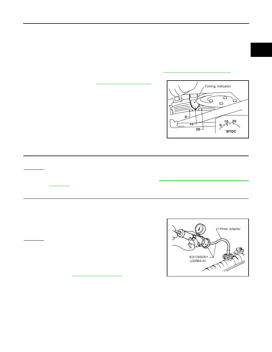
7.

Check ignition timing. Refer to 

EC-646, "Basic Inspection"

 .

Make sure that ignition timing is 10 

± 5° at 700 ± 50 rpm.

If NG, adjust ignition timing and then recheck.

Diagnostic Procedure

UBS00DJC

1. 

CHECK COOLING FAN (CRANKSHAFT DRIVEN) OPERATION

Start engine and make sure that cooling fan (crankshaft driven) operates.
OK or NG

OK

>> GO TO 2.

NG

>> Check cooling fan (crankshaft driven). Refer to 

CO-32, "COOLING FAN (CRANKSHAFT

DRIVEN)"

 . 

2. 

CHECK COOLING SYSTEM FOR LEAK

Apply pressure to the cooling system with a tester, and check if the pressure drops.

CAUTION:

Higher than the specified pressure may cause radiator damage.

Pressure should not drop. 

OK or NG

OK

>> GO TO 3.

NG

>> Check the following for leak:

Hose

Radiator

Water pump
Refer to 

CO-25, "WATER PUMP"

 .

SEF927Z

Testing pressure: 157 kPa (1.6 kg/cm

2

 , 23 psi)

SLC754A

EC-848

[VG33E]

DTC P0217 COOLANT OVERTEMPERATURE ENRICHMENT PROTECTION

3. 

CHECK RADIATOR CAP

Apply pressure to cap with a tester and check radiator cap relief
pressure.

OK or NG

OK

>> GO TO 4.

NG

>> Replace radiator cap.

4. 

CHECK THERMOSTAT

1.

Check valve seating condition at normal room temperatures.
It should seat tightly.

2.

Check valve opening temperature and valve lift.

3.

Check if valve is closed at 5

°C (9°F) below valve opening tem-

perature.

For details, refer to 

CO-28, "THERMOSTAT"

 .

OK or NG

OK

>> GO TO 5.

NG

>> Replace thermostat.

5. 

CHECK ENGINE COOLANT TEMPERATURE SENSOR

Check resistance as shown in the figure.
<Reference data>

OK or NG

OK

>> GO TO 6.

NG

>> Replace engine coolant temperature sensor.

Radiator cap 
relief pressure:

 59 - 98 kPa (0.6 - 1.0 kg/

cm

2

 , 9 - 14 psi)

SLC755A

Valve opening 
temperature

: 76.5

°C (170°F) [standard]

Valve lift

: More than 10 mm/90

°C (0.31 in/194°F)

SLC343

Temperature 

°C (°F)

Resistance k

20 (68)

2.1 - 2.9

50 (122)

0.68 - 1.00

90 (194)

0.236 - 0.260

SEF152P

SEF012P

DTC P0217 COOLANT OVERTEMPERATURE ENRICHMENT PROTECTION

EC-849

[VG33E]

C

D

E

F

G

H

I

J

K

L

M

A

EC

6. 

CHECK MAIN 12 CAUSES

If the cause cannot be isolated, go to 

EC-849, "Main 12 Causes of Overheating"

 .

>> INSPECTION END.

Main 12 Causes of Overheating

UBS00DJD

*1: Engine running at 3,000 rpm for 10 minutes.
*2: Drive at 90 km/h (55 MPH) for 30 minutes and then let idle for 10 minutes.
*3: After 60 minutes of cool down time.
For more information, refer to 

CO-21, "OVERHEATING CAUSE ANALYSIS"

 .

Engine

Step

Inspection item

Equipment

Standard

Reference page

OFF

1

Blocked radiator

Blocked condenser

Blocked radiator grille

Blocked bumper

Visual

No blocking

2

Coolant mixture

Coolant tester

50 - 50% coolant mixture

See 

MA-14

 .

3

Coolant level

Visual

Coolant up to MAX level 
in reservoir tank and radi-
ator filler neck

See 

MA-26

 .

4

Radiator cap

Pressure tester

59 - 98 kPa 

(0.6 - 1.0 kg/cm

2

 , 9 - 14 

psi) (Limit)

See 

CO-23

 .

ON*

1

5

Coolant leaks

Visual

No leaks

See 

CO-23

 .

ON*

1

6

Thermostat

Touch the upper and 
lower radiator hoses

Both hoses should be hot

See 

CO-28

 .

ON*

1

7

Cooling fan
(Crankshaft driven)

Visual

Operating

See

CO-32

 .

OFF

8

Combustion gas leak

Color checker chemical 
tester 4 Gas analyzer

Negative

ON*

2

9

Coolant temperature 
gauge

Visual

Gauge less than 3/4 
when driving

Coolant overflow to 
reservoir tank

Visual

No overflow during driv-
ing and idling

See 

MA-26

 .

OFF*

3

10

Coolant return from 
reservoir tank to radia-
tor

Visual

Should be initial level in 
reservoir tank

See 

CO-22

 .

OFF

11

Cylinder head

Straight gauge feeler 
gauge

0.1 mm (0.004 in) Maxi-
mum distortion (warping)

See 

EM-102

 .

12

Cylinder block and pis-
tons

Visual

No scuffing on cylinder 
walls or piston

 Se

EM-131

 .

EC-850

[VG33E]

DTC P0300 - P0306 MULTIPLE CYLINDER MISFIRE, NO. 1 - 6 CYLINDER MIS-

FIRE

DTC P0300 - P0306 MULTIPLE CYLINDER MISFIRE, NO. 1 - 6 CYLINDER MIS-
FIRE

PFP:00000

On Board Diagnosis Logic

UBS00DJE

When a misfire occurs, engine speed will fluctuate. If the engine speed fluctuates enough to cause the CKP
sensor signal to vary, ECM can determine that a misfire is occurring.

The misfire detection logic consists of the following two conditions.

1.

One Trip Detection Logic (Three Way Catalyst Damage)
On the first trip that a misfire condition occurs that can damage the three way catalyst (TWC) due to over-
heating, the MIL will blink.
When a misfire condition occurs, the ECM monitors the CKP sensor signal every 200 engine revolutions
for a change.
When the misfire condition decreases to a level that will not damage the TWC, the MIL will turn off.
If another misfire condition occurs that can damage the TWC on a second trip, the MIL will blink.
When the misfire condition decreases to a level that will not damage the TWC, the MIL will remain on.
If another misfire condition occurs that can damage the TWC, the MIL will begin to blink again.

2.

Two Trip Detection Logic (Exhaust quality deterioration)
For misfire conditions that will not damage the TWC (but will affect vehicle emissions), the MIL will only
light when the misfire is detected on a second trip. During this condition, the ECM monitors the CKP sen-
sor signal every 1,000 engine revolutions.
A misfire malfunction can be detected on any one cylinder or on multiple cylinders.

DTC Confirmation Procedure

UBS00DJF

CAUTION:

Always drive vehicle at a safe speed.

NOTE:
If DTC Confirmation Procedure has been previously conducted, always turn ignition switch OFF and wait at
least 5 seconds before conducting the next test.

Sensor

Input Signal to ECM

ECM function

Crankshaft position sensor (OBD)

Engine speed

On board diagnosis of misfire

DTC No.

Trouble diagnosis name

DTC detecting condition

Possible cause

P0300

Multiple cylinder misfire 
detected

Multiple cylinder misfire.

Improper spark plug

Insufficient compression

Incorrect fuel pressure

The injector circuit is open or shorted

Fuel injector

Intake air leak

The ignition secondary signal circuit is 
open or shorted

Lack of fuel

Signal plate or flywheel

Heated oxygen sensor 1

Incorrect PCV hose connection

P0301

No.1 cylinder misfire 
detected

No. 1 cylinder misfires.

P0302

No. 2 cylinder misfire 
detected

No. 2 cylinder misfires.

P0303

No. 3 cylinder misfire 
detected

No. 3 cylinder misfires.

P0304

No. 4 cylinder misfire 
detected

No. 4 cylinder misfires.

P0305

No. 5 cylinder misfire 
detected

No. 5 cylinder misfires.

P0306

No. 6 cylinder misfire 
detected

No. 6 cylinder misfires.


Content   ..  434  435  436  437   ..