Nissan Frontier D22. Manual - part 421
DTC P0133, P0153 HO2S1
EC-787
[VG33E]
C
D
E
F
G
H
I
J
K
L
M
A
EC
8.
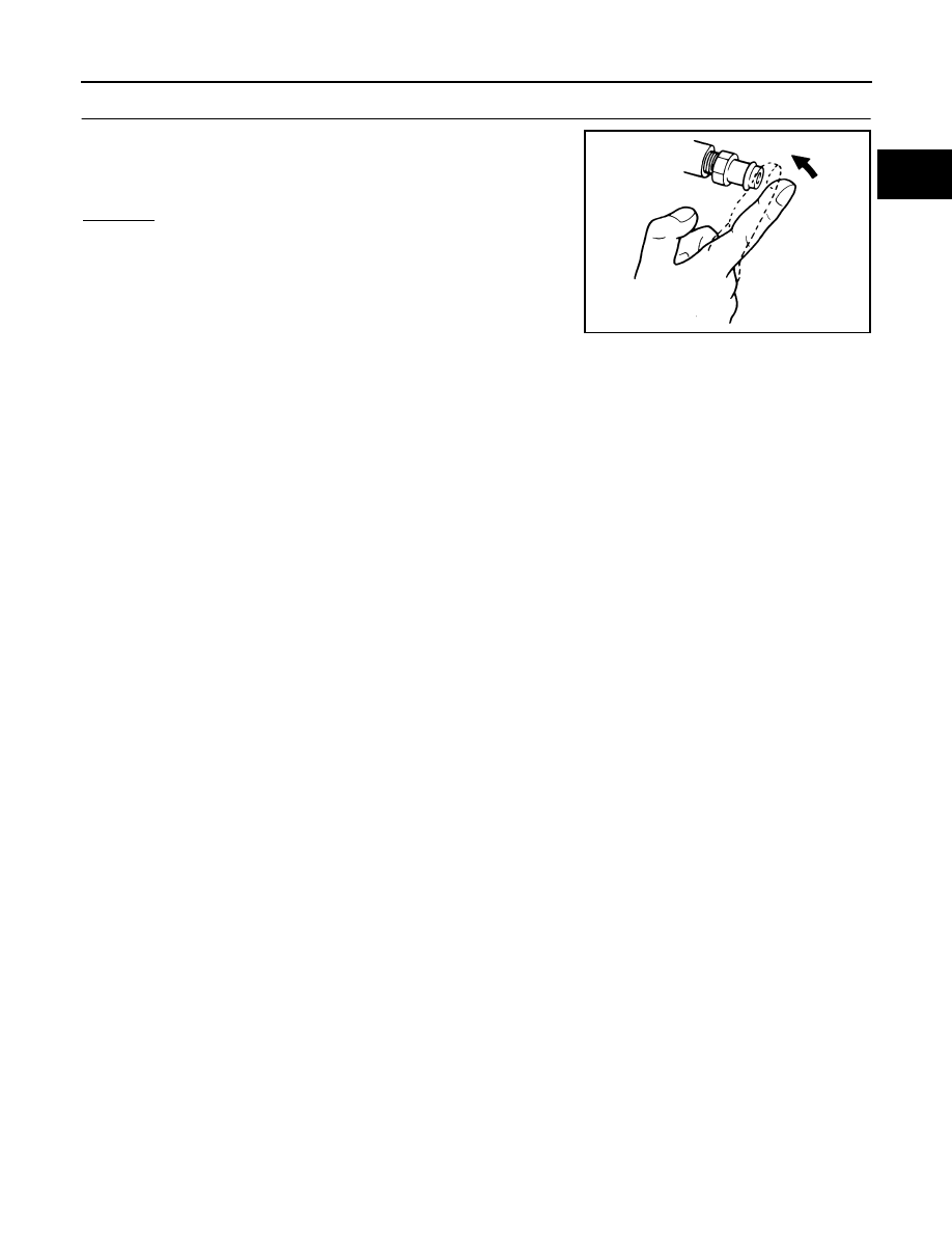
CHECK PCV VALVE
With engine running at idle, remove PCV valve from rocker cover;
make sure that a hissing noise will be heard as air passes through it
and a strong vacuum should be felt immediately when a finger is
placed over valve inlet.
OK or NG
OK (With CONSULT-II)>>GO TO 9.
OK (Without CONSULT-II)>>GO TO 10.
NG
>> Replace PCV valve.
SEC137A