Nissan Frontier D22. Manual - part 413
DTC P0122, P0123 TP SENSOR
EC-755
[VG33E]
C
D
E
F
G
H
I
J
K
L
M
A
EC
Specification data are reference values and are measured between each terminal and ground.
CAUTION:
Do not use ECM ground terminals when measuring input/output voltage. Doing so may result in dam-
age to the ECM's transistor. Use a ground other than the ECM terminals, such as the ground.
Diagnostic Procedure
UBS00DH6
1.
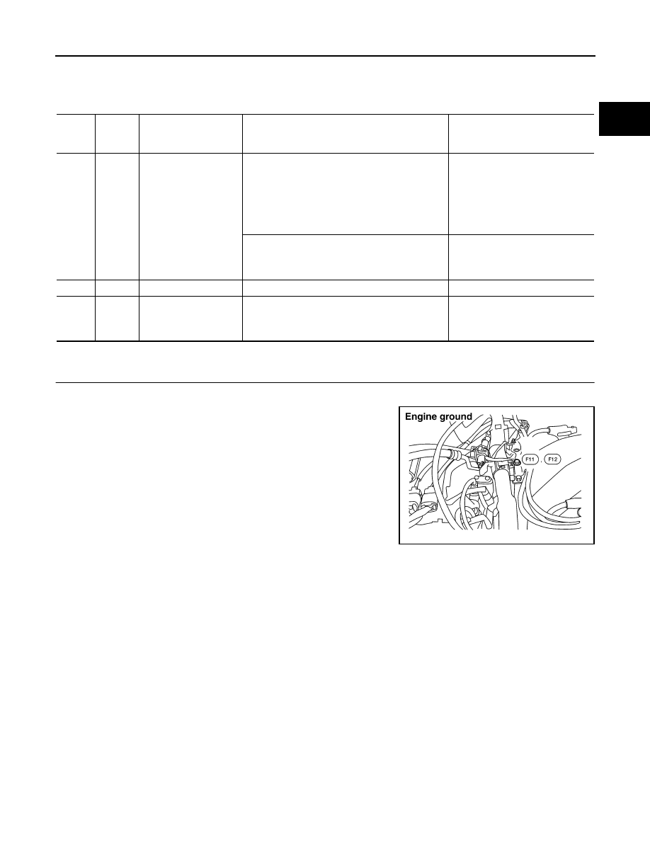
RETIGHTEN GROUND SCREWS
1.
Turn ignition switch OFF.
2.
Loosen and retighten engine ground screws.
>> GO TO 2.
TER-
MINAL
NO.
WIRE
COLOR
ITEM
CONDITION
DATA (DC Voltage)
23
L
Throttle position sensor
[Engine is running]
●
Warm-up condition
●
More than -40.0 kpa (-300 mmHg, -11.81 inHg)
of vacuum is applied to the throttle opener with
a hand vacuum pump
●
Accelerator pedal is fully released
0.15 - 0.85V
[Ignition switch: ON]
●
Engine stopped
●
Accelerator pedal is fully depressed
3.5 - 4.7V
42
B/W
Sensor power supply
[Ignition switch: ON]
Approximately 5V
43
BR
Sensor ground
[Engine is running]
●
Warm-up condition
●
Idle speed
Approximately 0V
BBIA0418E