Nissan Frontier D22. Manual - part 410


  Index      Nissan     Nissan Frontier D22 Pickup (1998-2004 year) - Service and Repair Manual


Search            


Content   ..  408  409  410  411   ..


Nissan Frontier D22. Manual - part 410


DTC P0121 TP SENSOR

EC-743

[VG33E]

C

D

E

F

G

H

I

J

K

L

M

A

EC

DTC P0121 TP SENSOR

PFP:16119

Component Description

UBS00DGU

NOTE:
If DTC P0121 is displayed with DTC P0510, first perform the trouble diagnosis for DTC P0510. Refer to

EC-992

 .

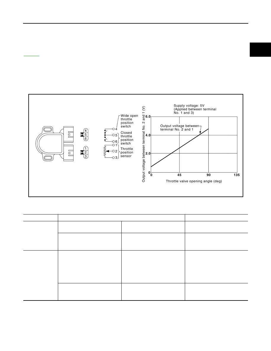
The throttle position sensor responds to the accelerator pedal movement. This sensor is a kind of potentiome-
ter which transforms the throttle position into output voltage, and emits the voltage signal to the ECM. In addi-
tion, the sensor detects the opening and closing speed of the throttle valve and feeds the voltage signal to the
ECM.
Idle position of the throttle valve is determined by the ECM receiving the signal from the throttle position sen-
sor. This sensor controls engine operation such as fuel cut. On the other hand, the “Wide open and closed
throttle position switch”, which is built into the throttle position sensor unit, is not used for engine control.

CONSULT-II Reference Value in Data Monitor Mode

UBS00DGV

Specification data are reference values.

SEF349X

MONITOR ITEM

CONDITION

SPECIFICATION

THRTL POS SEN

Engine: After warming up, idle the 
engine

Throttle valve: fully closed

0.15 - 0.85V

Engine: After warming up

Ignition switch: ON
(Engine stopped)

Throttle valve: fully opened

3.5 - 4.7V

ABSOL TH·P/S

Engine: After warming up

Ignition switch: ON

More than -40.0 kpa (-300 mmHg, 
-11.81 inHg) of vacuum is applied 
to the throttle opener with a hand 
vacuum pump.

Throttle valve: fully closed

0.0%

Engine: After warming up

Ignition switch: ON
(Engine stopped)

Throttle valve: fully opened

Approx. 80%

EC-744

[VG33E]

DTC P0121 TP SENSOR

On Board Diagnosis Logic

UBS00DGW

DTC Confirmation Procedure

UBS00DGX

NOTE:

Perform PROCEDURE FOR MALFUNCTION A first. If the 1st trip DTC cannot be confirmed, per-
form PROCEDURE FOR MALFUNCTION B.

If DTC Confirmation Procedure has been previously conducted, always turn ignition switch OFF and wait
at least 5 seconds before conducting the next test.

PROCEDURE FOR MALFUNCTION A

 With CONSULT-II

1.

Turn ignition switch ON.

2.

Select “DATA MONITOR” mode with CONSULT-II.

3.

Start engine and let it idle for at least 10 seconds.
If idle speed is over 1,000 rpm, maintain the following conditions
for at least 10 seconds to keep engine speed below 1,000 rpm.

4.

If 1st trip DTC is detected, go to 

EC-747, "Diagnostic Procedure"

.

 With GST

Follow the procedure “With CONSULT-II”.

PROCEDURE FOR MALFUNCTION B

CAUTION:

Always drive vehicle at a safe speed.

 With CONSULT-II

1.

Start engine and warm it up to normal operating temperature.

2.

Turn ignition switch OFF and wait at least 5 seconds.

3.

Turn ignition switch ON.

4.

Select “MANU TRIG” in “DATA MONITOR” mode with CONSULT-II.

DTC No.

Trouble diagnosis name

DTC detecting condition

Possible cause

P0121

Throttle position sensor cir-
cuit range/performance prob-
lem

A)

A high voltage from the sensor is 
sent to ECM under light load driving 
condition.

Harness or connectors
(The TP sensor circuit is open or 
shorted.)

TP sensor

Fuel injector

Camshaft position sensor

Mass air flow sensor

B)

A low voltage from the sensor is 
sent to ECM under heavy load driv-
ing condition.

Harness or connectors
(The TP sensor circuit is open or 
shorted.)

Intake air leaks

TP sensor

Selector lever

Suitable position except P or N (A/T), Neutral (M/T)

Brake pedal

Depressed

Vehicle speed

0 km/h (0 MPH)

SEF058Y

DTC P0121 TP SENSOR

EC-745

[VG33E]

C

D

E

F

G

H

I

J

K

L

M

A

EC

5.

Select “THRTL POS SEN” and “ABSOL TH·P/S” in “DATA MON-
ITOR” mode with CONSULT-II.

6.

Press RECORD on CONSULT-II screen at the same time accel-
erator pedal is depressed.

7.

Print out the recorded graph and check the following:

The voltage rise is linear in response to accelerator pedal
depression.

The voltage when accelerator pedal is fully depressed is approx-
imately 4V.
If NG, go to 

EC-747, "Diagnostic Procedure"

 .

If OK, go to following step.

8.

Select  “AUTO TRIG” in “DATA MONITOR” mode with CON-
SULT-II.

9.

Maintain the following conditions for at least 10 consecutive sec-
onds.

10. If 1st trip DTC is detected, go to 

EC-747, "Diagnostic Procedure"

 . 

 With GST

Follow the procedure “With CONSULT-II”.

CMPS·RPM (REF)

More than 2,000 rpm

MAS AIR/FL SE

More than 3V

COOLAN TEMP/S

More than 70

°C (158°F)

IACV-AAC/V

Less than 80%

Selector lever

Suitable position

Driving location

Driving vehicle uphill (Increased engine load) will 
help maintain the driving conditions required for 
this test.

SEF177Y

SEF174Z

SEF805Z

EC-746

[VG33E]

DTC P0121 TP SENSOR

Wiring Diagram

UBS00DGY

BBWA0473E


Content   ..  408  409  410  411   ..