Nissan Frontier D22. Manual - part 385


  Index      Nissan     Nissan Frontier D22 Pickup (1998-2004 year) - Service and Repair Manual


Search            


Content   ..  383  384  385  386   ..


Nissan Frontier D22. Manual - part 385


TROUBLE DIAGNOSIS

EC-643

[VG33E]

C

D

E

F

G

H

I

J

K

L

M

A

EC

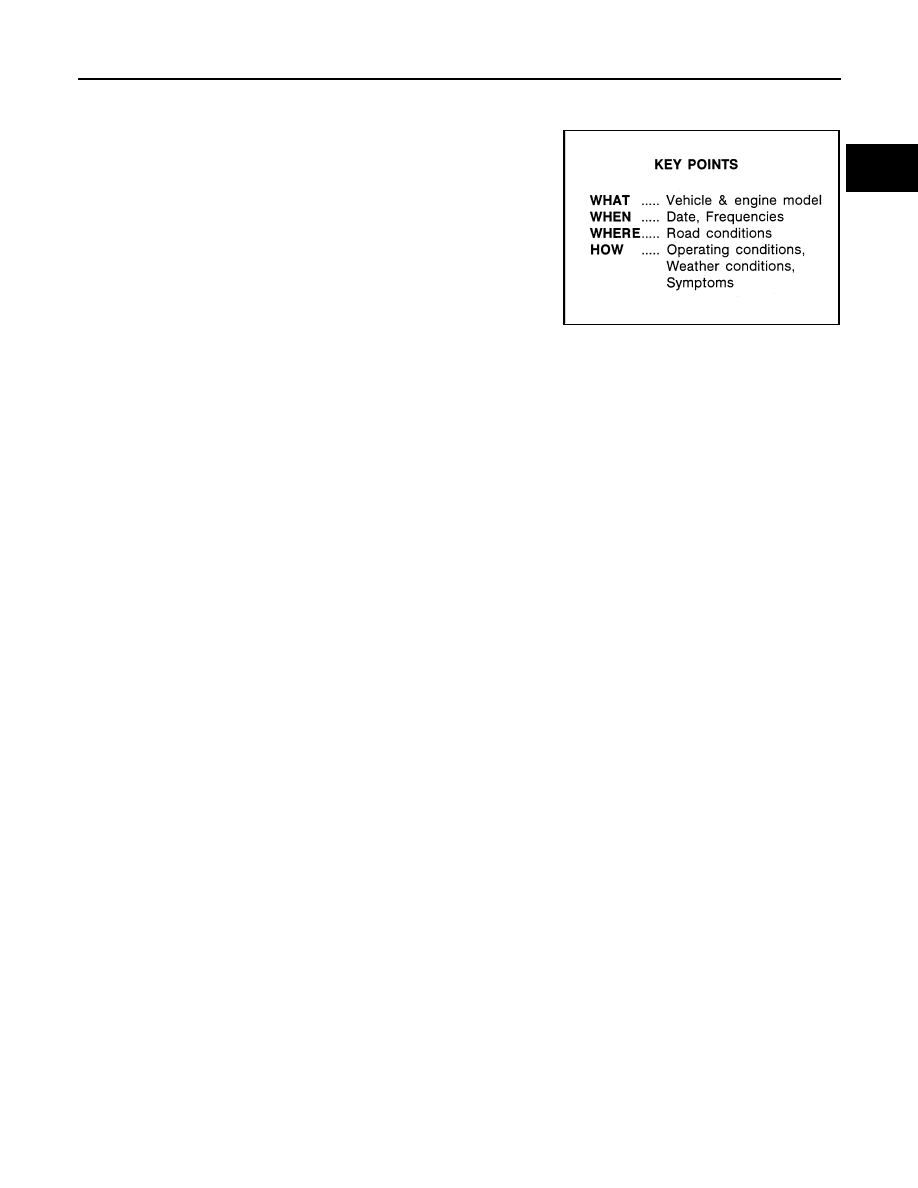
DIAGNOSTIC WORKSHEET
Description

There are many operating conditions that lead to the malfunction of
engine components. A good grasp of such conditions can make trou-
ble-shooting faster and more accurate.
In general, each customer feels differently about a incident. It is
important to fully understand the symptoms or conditions for a cus-
tomer complaint.
Utilize a diagnostic worksheet like the one on the next page in order
to organize all the information for troubleshooting.
Some conditions may cause the MIL to come on steady or blink and
DTC to be detected. Examples:

Vehicle ran out of fuel, which caused the engine to misfire.

Fuel filler cap was left off or incorrectly screwed on, allowing fuel
to evaporate into the atmosphere.

SEF907L

EC-644

[VG33E]

TROUBLE DIAGNOSIS

Worksheet Sample

LEC031A

TROUBLE DIAGNOSIS

EC-645

[VG33E]

C

D

E

F

G

H

I

J

K

L

M

A

EC

DTC Inspection Priority Chart

UBS00DF2

If some DTCs are displayed at the same time, perform inspections one by one based on the following priority
chart.

Priority

Detected items (DTC)

1

P0101, P0102, P0103 Mass air flow sensor 

P0112, P0113, P0127 Intake air temperature sensor

P0117, P0118, P0125 Engine coolant temperature sensor

P0121, P0122, P0123 Throttle position sensor

P0181, P0182, P0183 Fuel tank temperature sensor

P0327, P0328 Knock sensor

P0335 P1336 CKP sensor (OBD)

P0340 CMP sensor

P0460 P0461 P1464 Fuel level sensor

P0500 VSS

P0600 A/T control

P0605 ECM

P1400 EGRC-solenoid valve

P1605 A/T diagnosis communication line

P1706 PNP switch

2

P0132-P0134, P1143, P1144/P0152-P0154, P1163, P1164 HO2S1

P0031, P0032/P0051, P0052 HO2S1 heater

P0138, P0139, P1146, P1147/P0158, P0159, P1166, P1167 HO2S2

P0037, P0038/P0057, P0058 HO2S2 heater

P0217 Engine coolant overtemperature enrichment protection

P0405, P0406 EGR temperature sensor

P0441 EVAP control system purge flow monitoring

P0444, P0445, P1444 EVAP canister purge volume control solenoid valve

P0447, P1446, P1448 EVAP canister vent control valve 

P0452, P0453 EVAP control system pressure sensor 

 P0456, P1456 EVAP control system

P0510 CTP switch

P0705-P0755, P1705, P1760 A/T related sensors, solenoid valves and switches

P1490 P1491 Vacuum cut valve bypass valve

3

P0171, P0172, P0174, P0175 Fuel injection system function

P0306 - P0300 Misfire

P0400, P1402 EGR function

P0402 EGRC-BPT valve function

P0420, P0430 Three way catalyst function 

P0442/P1442 EVAP control system

P0455 EVAP control system

P0505 ISC valve

P0731-P0734 P0744 A/T function

P1148, P1168 Closed loop control

EC-646

[VG33E]

TROUBLE DIAGNOSIS

Fail-safe Chart

UBS00DF3

When the DTC listed below is detected, the ECM enters the fail-sate mode and the MIL illuminates.

Basic Inspection

UBS00DF4

Precaution:
Perform Basic Inspection without electrical or mechanical loads applied;

Headlamp switch is OFF,

Air conditioner switch is OFF,

Rear window defogger switch is OFF,

Steering wheel is in the straight-ahead position, etc.

DTC No.

Detected items

Engine operating condition in fail-safe mode

P0102
P0103

Mass air flow sensor circuit

Engine speed will not rise more than 2,400 rpm due to the fuel cut.

P0117
P0118

Engine coolant temperature 
sensor circuit

Engine coolant temperature will be determined by ECM based on the time after turning 
ignition switch ON or START.
CONSULT-II displays the engine coolant temperature decided by ECM.

Condition

Engine coolant temperature decided (CONSULT-II 

display)

Just as ignition switch is turned ON 
or START

40

°C (104°F)

More than approx. 4 minutes after 
ignition ON or START

80

°C (176°F)

Except as shown above

40 - 80

°C (104 - 176°F)

(Depends on the time)

P0122
P0123

Throttle position sensor cir-
cuit

Throttle position will be determined based on the injected fuel amount and the engine 
speed.
Therefore, acceleration will be poor.

Condition

Driving condition

When engine is idling

Normal

When accelerating

Poor acceleration

Unable to 

access ECM

ECM

ECM fail-safe activating condition 
The computing function of the ECM was judged to be malfunctioning.
When the fail-safe system activates (i.e., if the ECM detects a malfunction condition in 
the CPU of ECM), the MIL on the instrument panel lights to warn the driver.
However it is not possible to access ECM and DTC cannot be confirmed.
Engine control with fail-safe
When ECM fail-safe is operating, fuel injection, ignition timing, fuel pump operation, and 
IACV-AAC valve operation are controlled under certain limitations.

ECM fail-safe operation

Engine speed

Engine speed will not rise more than 3,000 rpm

Fuel injection

Simultaneous multiport fuel injection system

Ignition timing

Ignition timing is fixed at the preset value

Fuel pump

Fuel pump relay is ON when engine is running 

and OFF when engine stalls

IACV-AAC valve

 Full open

Replace ECM, if ECM fail-safe condition is confirmed.


Content   ..  383  384  385  386   ..