Nissan Frontier D22. Manual - part 384


  Index      Nissan     Nissan Frontier D22 Pickup (1998-2004 year) - Service and Repair Manual


Search            


Content   ..  382  383  384  385   ..


Nissan Frontier D22. Manual - part 384


ON BOARD DIAGNOSTIC (OBD) SYSTEM

EC-639

[VG33E]

C

D

E

F

G

H

I

J

K

L

M

A

EC

EXPLANATION FOR DRIVING PATTERNS EXCEPT  FOR “MISFIRE <EXHAUST QUALITY 
DETERIORATION>”, “FUEL INJECTION SYSTEM”
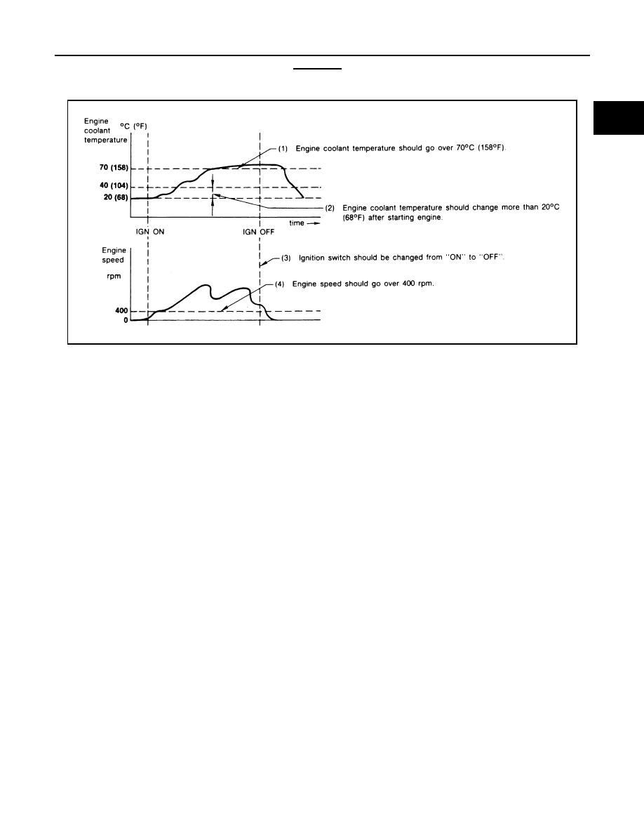
<Driving Pattern A>

The A counter will be cleared when the malfunction is detected regardless of (1) - (4).

The A counter will be counted up when (1) - (4) are satisfied without the same malfunction.

The DTC will not be displayed after the A counter reaches 40.

<Driving Pattern B>

Driving pattern B means the vehicle operation as follows:
All components and systems should be monitored at least once by the OBD system.

The B counter will be cleared when the malfunction is detected once regardless of the driving pattern.

The B counter will be counted up when driving pattern B is satisfied without any malfunctions.

The MIL will go off when the B counter reaches 3 (*2 in OBD SYSTEM OPERATION CHART).

AEC574

EC-640

[VG33E]

TROUBLE DIAGNOSIS

TROUBLE DIAGNOSIS

PFP:00004

Trouble Diagnosis Introduction

UBS00DF1

INTRODUCTION

The engine has an ECM to control major systems such as fuel con-
trol, ignition control, idle air control system, etc. The ECM accepts
input signals from sensors and instantly drives actuators. It is essen-
tial that both input and output signals are proper and stable. At the
same time, it is important that there are no malfunctions such as vac-
uum leaks, fouled spark plugs, or other malfunctions with the engine.

It is much more difficult to diagnose a incident that occurs intermit-
tently rather than continuously. Most intermittent incidents are
caused by poor electric connections or improper wiring. In this case,
careful checking of suspected circuits may help prevent the replace-
ment of good parts.

A visual check only may not find the cause of the incidents. A road
test with CONSULT-II (or GST) or a circuit tester connected should
be performed. Follow the 

EC-641, "WORK FLOW"

 .

Before undertaking actual checks, take a few minutes to talk with a
customer who approaches with a driveability complaint. The cus-
tomer can supply good information about such incidents, especially
intermittent ones. Find out what symptoms are present and under
what conditions they occur. A Diagnostic Worksheet like the example
on next page should be used.
Start your diagnosis by looking for conventional malfunctions first.
This will help troubleshoot driveability malfunctions on an electroni-
cally controlled engine vehicle.

MEF036D

SEF233G

SEF234G

TROUBLE DIAGNOSIS

EC-641

[VG33E]

C

D

E

F

G

H

I

J

K

L

M

A

EC

WORK FLOW
Flow Chart

*1

If time data of “SELF-DIAG 
RESULTS” is other than [0] or [1t], 
perform 

EC-696, "TROUBLE DIAG-

NOSIS FOR INTERMITTENT INCI-
DENT"

 .

*2

If the incident cannot be verified, per-
form 

EC-696, "TROUBLE DIAGNO-

SIS FOR INTERMITTENT 
INCIDENT"

 .

*3

If the on board diagnostic system 
cannot be performed, check main 
power supply and ground circuit. 
Refer to 

EC-697, "POWER SUPPLY 

CIRCUIT FOR ECM"

 .

*4

If malfunctioning part cannot be 
detected, perform 

EC-696, "TROU-

BLE DIAGNOSIS FOR INTERMIT-
TENT INCIDENT"

 .

*5

EC-629, "Driving Pattern"

.

*6

EC-692, "TROUBLE DIAGNOSIS - 
SPECIFICATION VALUE"

.

PBIB1043E

EC-642

[VG33E]

TROUBLE DIAGNOSIS

Description For Work Flow

STEP

DESCRIPTION

STEP I

Get detailed information about the conditions and the environment when the incident/symptom occurred using the 

EC-643, "DIAGNOSTIC WORKSHEET"

 .

STEP II

Before confirming the concern, check and write down (print out using CONSULT-II or GST) the (1st trip) DTC and the 
(1st trip) freeze frame data, then erase the DTC and the data. (Refer to 

EC-632

 .) The (1st trip) DTC and the (1st trip) 

freeze frame data can be used when duplicating the incident at STEP III & IV.
If the incident cannot be verified, perform 

EC-696, "TROUBLE DIAGNOSIS FOR INTERMITTENT INCIDENT"

 .

Study the relationship between the cause, specified by (1st trip) DTC, and the symptom described by the customer. 
(The Symptom Matrix Chart will be useful. See 

EC-659

 .)

Also check related service bulletins for information.

STEP III

Try to confirm the symptom and under what conditions the incident occurs.
The DIAGNOSTIC WORK SHEET and the freeze frame data are useful to verify the incident. Connect CONSULT-II to 
the vehicle in “DATA MONITOR (AUTO TRIG)” mode and check real time diagnosis results.
If the incident cannot be verified, perform 

EC-696, "TROUBLE DIAGNOSIS FOR INTERMITTENT INCIDENT"

 .

If the malfunction code is detected, skip STEP IV and perform STEP V.

STEP IV

Try to detect the (1st trip) DTC by driving in (or performing) the DTC Confirmation Procedure. Check and read the (1st 
trip) DTC and (1st trip) freeze frame data by using CONSULT-II or GST.
During the (1st trip) DTC verification, be sure to connect CONSULT-II to the vehicle in “DATA MONITOR (AUTO 
TRIG)” mode and check real time diagnosis results.
If the incident cannot be verified, perform 

EC-696, "TROUBLE DIAGNOSIS FOR INTERMITTENT INCIDENT"

 .

In case the DTC Confirmation Procedure is not available, perform the Overall Function Check instead. The (1st trip) 
DTC cannot be displayed by this check, however, this simplified check is an effective alternative.
The NG result of the Overall Function Check is the same as the (1st trip) DTC detection.

STEP V

Take the appropriate action based on the results of STEP I through IV.
If the malfunction code is indicated, proceed to TROUBLE DIAGNOSIS FOR DTC PXXXX.
If the normal code is indicated, proceed to the BASIC INSPECTION. (Refer to 

EC-646

 .) If CONSULT-II is available, 

perform “DATA MONITOR (SPEC)” mode with CONSULT-II and proceed to the 

EC-692, "TROUBLE DIAGNOSIS - 

SPECIFICATION VALUE"

 . (If malfunction is detected, proceed to REPAIR/REPLACE.) Then perform inspections 

according to the Symptom Matrix Chart. (Refer to 

EC-659

 .)

STEP VI

Identify where to begin diagnosis based on the relationship study between symptom and possible causes. Inspect the 
system for mechanical binding, loose connectors or wiring damage using (tracing) Harness Layouts.
Gently shake the related connectors, components or wiring harness with CONSULT-II set in “DATA MONITOR (AUTO 
TRIG)” mode.
Check the voltage of the related ECM terminals or monitor the output data from the related sensors with CONSULT-II. 
Refer to 

EC-667

 , 

EC-687

 .

The Diagnostic Procedure in EC section contains a description based on open circuit inspection. A short circuit 
inspection is also required for the circuit check in the Diagnostic Procedure. For details, refer to 

GI-25, "How to Per-

form Efficient Diagnosis for an Electrical Incident"

 .

Repair or replace the malfunction parts.
If malfunctioning part cannot be detected, perform 

EC-696, "TROUBLE DIAGNOSIS FOR INTERMITTENT INCI-

DENT"

 .

STEP VII

Once you have repaired the circuit or replaced a component, you need to run the engine in the same conditions and 
circumstances which resulted in the customer's initial complaint.
Perform the DTC Confirmation Procedure and confirm the normal code [DTC No. P0000] is detected. If the incident is 
still detected in the final check, perform STEP VI by using a different method from the previous one.
Before returning the vehicle to the customer, be sure to erase the unnecessary (already fixed) (1st trip) DTC in ECM 
and TCM (Transmission control module). (Refer to 

EC-632

  and 

AT-187

 .)


Content   ..  382  383  384  385   ..