Nissan Frontier D22. Manual - part 354
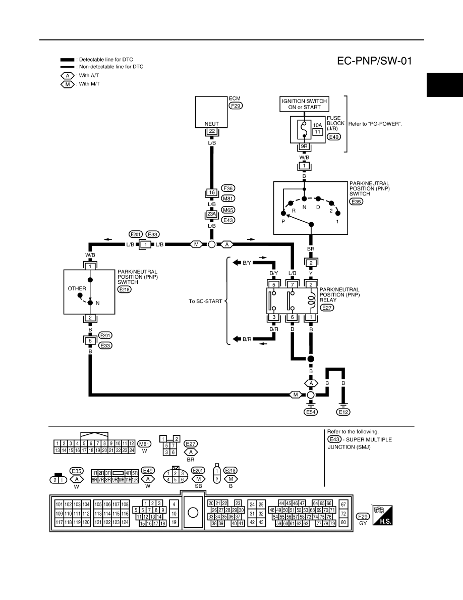
DTC P1706 PNP SWITCH
EC-519
[KA24DE]
C
D
E
F
G
H
I
J
K
L
M
A
EC
Wiring Diagram
UBS00DCJ
BBWA1068E
|
|
|
DTC P1706 PNP SWITCH EC-519 [KA24DE] C D E F G H I J K L M A EC Wiring Diagram UBS00DCJ BBWA1068E |