Nissan Frontier D22. Manual - part 352
 

  Index      Nissan     Nissan Frontier D22 Pickup (1998-2004 year) - Service and Repair Manual


Search            


Content   ..  350  351  352  353   ..


Nissan Frontier D22. Manual - part 352


DTC P1491 VACUUM CUT VALVE BYPASS VALVE

EC-511

[KA24DE]

C

D

E

F

G

H

I

J

K

L

M

A

EC

Specification data are reference values and are measured between each terminal and ground.

CAUTION:

Do not use ECM ground terminals when measuring input/output voltage. Doing so may result in dam-
age to the ECM's transistor. Use a ground other than ECM terminals, such as the ground.

Diagnostic Procedure

UBS00DCD

1. 

INSPECTION START

Do you have CONSULT-II?

Yes or No

Yes

>> GO TO 2.

No

>> GO TO 3.

2. 

CHECK COMPONENT

 With CONSULT-II

1.

Turn ignition switch OFF.

2.

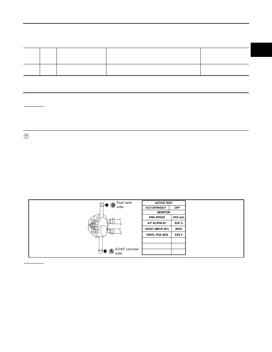
Remove vacuum cut valve and vacuum cut valve bypass valve as an assembly.

3.

Apply vacuum to port A and check that there is no suction from port B.

4.

Apply vacuum to port B and check that there is suction from port A.

5.

Blow air in port B and check that there is a resistance to flow out of port A.

6.

Turn ignition switch ON.

7.

Select “VC/V BYPASS/V” in “ACTIVE TEST” mode with CONSULT-II and touch “ON”.

8.

Blow air in port A and check that air flows freely out of port B.

9.

Blow air in port B and check that air flows freely out of port A.

OK or NG

OK

>> GO TO 4.

NG

>> GO TO 5.

TER-

MINAL 

NO.

WIRE 

COLO

R

ITEM

CONDITION

DATA (DC Voltage)

120

P/B

Vacuum cut valve bypass 
valve

[Ignition switch: ON]

BATTERY VOLTAGE
(11 - 14V)

SEF808Y

EC-512

[KA24DE]

DTC P1491 VACUUM CUT VALVE BYPASS VALVE

3. 

CHECK COMPONENT

 Without CONSULT-II

1.

Turn ignition switch OFF.

2.

Remove vacuum cut valve and vacuum cut valve bypass valve as an assembly.

3.

Apply vacuum to port A and check that there is no suction from port B.

4.

Apply vacuum to port B and check that there is suction from port A.

5.

Blow air in port B and check that there is a resistance to flow out of port A.

6.

Disconnect vacuum cut valve bypass valve harness connector.

7.

Supply battery voltage to the terminal.

8.

Blow air in port A and check that air flows freely out of port B.

9.

Blow air in port B and check that air flows freely out of port A.

OK or NG

OK

>> GO TO 4.

NG

>> GO TO 5.

4. 

CHECK EVAP PURGE LINE

1.

Check EVAP purge line between EVAP canister and fuel tank for clogging or disconnection.

2.

Check EVAP purge port of fuel tank for clogging.

3.

Check EVAP canister. Refer to 

EC-567, "Component Inspection"

 .

OK or NG

OK

>> GO TO 8.

NG (Step 1)>>Repair it.
NG (Step 2)>>Clean EVAP purge port.
NG (Step 3)>>Replace EVAP canister.

5. 

CHECK BYPASS HOSE

Check bypass hoses for clogging.

OK or NG

OK

>> GO TO 6.

NG

>> Repair or replace hoses.

SEF914U

DTC P1491 VACUUM CUT VALVE BYPASS VALVE

EC-513

[KA24DE]

C

D

E

F

G

H

I

J

K

L

M

A

EC

6. 

CHECK VACUUM CUT VALVE BYPASS VALVE

 With CONSULT-II

Check air passage continuity.
Perform “VC/V BYPASS/V” in “ACTIVE TEST” mode.

 Without CONSULT-II

Check air passage continuity shown in the figure.

OK or NG

OK

>> GO TO 7.

NG

>> Replace vacuum cut valve bypass valve.

7. 

CHECK VACUUM CUT VALVE

Check vacuum cut valve as follows:

1.

Plug port C  and D  with fingers.

2.

Apply vacuum to port A  and check that there is no suction from
port B .

3.

Apply vacuum to port B  and check that there is suction from
port A .

4.

Blow air in port B  and check that there is a resistance to flow out
of port A .

5.

 Open port C  and D .

6.

Blow air in port A  check that air flows freely out of port C .

7.

Blow air in port B  check that air flows freely out of port D .

OK or NG

OK

>> GO TO 8.

NG

>> Replace vacuum cut valve.

SEF807Y

SEF557Y

SEF186S

SEF379Q

EC-514

[KA24DE]

DTC P1491 VACUUM CUT VALVE BYPASS VALVE

8. 

CHECK EVAP CONTROL SYSTEM PRESSURE SENSOR HOSE

1.

Turn ignition switch OFF.

2.

Check disconnection or improper connection of hose connected to EVAP control system pressure sensor.

OK or NG

OK

>> GO TO 9.

NG

>> Repair it

9. 

CHECK CONNECTOR

1.

Disconnect EVAP control system pressure sensor harness con-
nector.

2.

Check connectors for water.
Water should not exist.

OK or NG

OK

>> GO TO 10.

NG

>> Replace EVAP control system pressure sensor.

10. 

CHECK EVAP CONTROL SYSTEM PRESSURE SENSOR

Perform “DTC Confirmation Procedure”, for DTC P0452, 

EC-339

  and DTC P0453, 

EC-346

 .

OK or NG

OK

>> GO TO 11.

NG

>> Replace EVAP control system pressure sensor.

11. 

CHECK EVAP CANISTER VENT CONTROL VALVE-I

1.

Remove EVAP canister vent control valve from EVAP canister.

2.

Check portion B  of EVAP canister vent control valve for being
rusted.

 OK or NG

OK

>> GO TO 12.

NG

>> Replace EVAP canister vent control valve.

SEF341V

BBIA0308E


Content   ..  350  351  352  353   ..