Nissan Frontier D22. Manual - part 319


  Index      Nissan     Nissan Frontier D22 Pickup (1998-2004 year) - Service and Repair Manual


Search            


Content   ..  317  318  319  320   ..


Nissan Frontier D22. Manual - part 319


DTC P0460 FUEL LEVEL SENSOR

EC-379

[KA24DE]

C

D

E

F

G

H

I

J

K

L

M

A

EC

Diagnostic Procedure

UBS00D8F

1. 

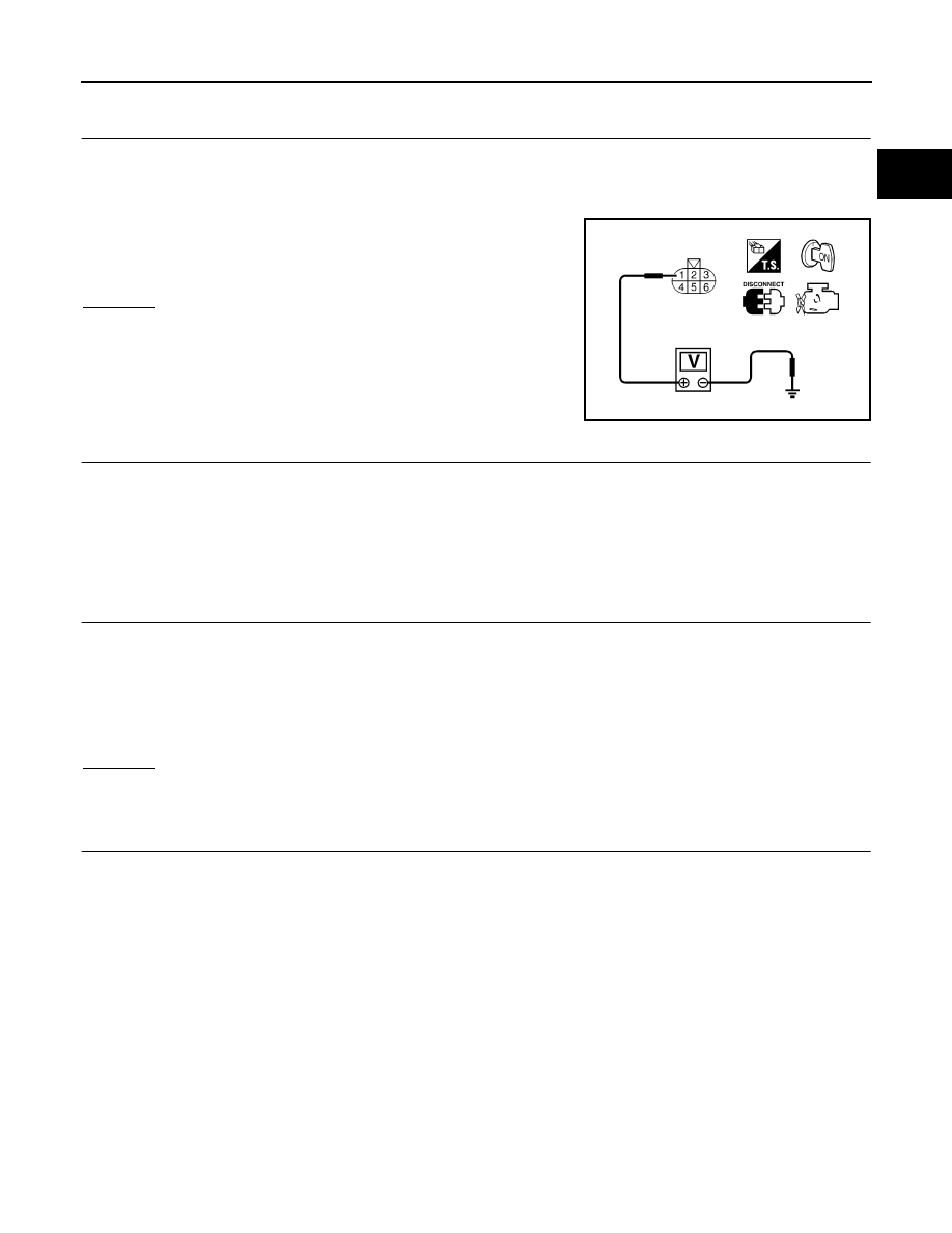
CHECK FUEL LEVEL SENSOR POWER SUPPLY CIRCUIT

1.

Turn ignition switch OFF.

2.

Disconnect fuel level sensor unit and fuel pump harness connector.

3.

Turn ignition switch ON.

4.

Check voltage between fuel level sensor unit and fuel pump ter-
minal 1 and ground with CONSULT-II or a tester.

OK or NG

OK

>> GO TO 3.

NG

>> GO TO 2.

2. 

DETECT MALFUNCTIONING PART

Check the following.

Harness connectors M67, C1

Harness for open or short between combination meter and fuel level sensor until and fuel pump

>> Repair or replace harness or connectors.

3. 

CHECK FUEL LEVEL SENSOR GROUND CIRCUIT FOR OPEN AND SHORT

1.

Turn ignition switch OFF.

2.

Check harness continuity between fuel level sensor unit terminal 4 and body ground.
Refer to Wiring Diagram.

3.

Also check harness for short to power.

OK or NG

OK

>> GO TO 5.

NG

>> GO TO 4.

4. 

DETECT MALFUNCTIONING PART

Check the following.

Harness connectors M67, C1

Harness for open or short between fuel level sensor and body ground

>> Repair open circuit or short to power in harness or connectors.

Voltage

: Battery voltage

SEF863Z

Continuity should exist.

EC-380

[KA24DE]

DTC P0460 FUEL LEVEL SENSOR

5. 

CHECK FUEL LEVEL SENSOR INPUT SIGNAL CIRCUIT FOR OPEN AND SHORT

1.

Disconnect ECM harness connector.

2.

Check harness continuity between ECM terminal 46 and fuel level sensor unit terminal 1, ECM terminal
66 and fuel level sensor unit terminal 4.
Refer to Wiring Diagram.

3.

Also check harness for short to power.

OK or NG

OK

>> GO TO 7.

NG

>> GO TO 6.

6. 

DETECT MALFUNCTIONING PART

Check the following.

Harness connectors M81, F36

Harness connectors M67, C1

Harness for open or short between ECM and fuel level sensor

>> Repair open circuit or short to ground or short to power in harness or connectors.

7. 

CHECK FUEL LEVEL SENSOR

Refer to 

DI-19, "VEHICLE SPEED SENSOR SIGNAL CHECK"

 .

OK or NG

OK

>> GO TO 8.

NG

>> Replace fuel level sensor unit.

8. 

CHECK INTERMITTENT INCIDENT

Refer to 

EC-120, "TROUBLE DIAGNOSIS FOR INTERMITTENT INCIDENT"

 .

>> INSPECTION END.

Removal and Installation

UBS00D8G

FUEL LEVEL SENSOR

Refer to 

FL-6, "FUEL LEVEL SENSOR UNIT AND FUEL PUMP ASSEMBLY"

 .

Continuity should exist.

DTC P0461 FUEL LEVEL SENSOR

EC-381

[KA24DE]

C

D

E

F

G

H

I

J

K

L

M

A

EC

DTC P0461 FUEL LEVEL SENSOR

PFP:25060

Component Description

UBS00D8H

The fuel level sensor is mounted in the fuel level sensor unit. The
sensor detects a fuel level in the fuel tank and transmits a signal to
the ECM.
It consists of two parts, one is mechanical float and the other is vari-
able resistor. Fuel level sensor output voltage changes depending on
the movement of the fuel mechanical float.

On Board Diagnostic Logic

UBS00D8I

Driving long distances naturally affects fuel gauge level.
This diagnosis detects the fuel gauge malfunction of the gauge not moving even after a long distance has
been driven.
Malfunction is detected when the output signal of the fuel level sensor does not change within the specified
range even though the vehicle has been driven a long distance.

Overall Function Check

UBS00D8J

Use this procedure to check the overall function of the fuel level sensor function. During this check, a 1st trip
DTC might not be confirmed.

WARNING:

When performing following procedure, be sure to observe the handling of the fuel. Refer to 

FL-3,

"FUEL TANK"

 .

TESTING CONDITION:
Before starting overall function check, preparation of draining fuel and refilling fuel is required.

WITH CONSULT-II

NOTE:
Start from step 10, if it is possible to confirm that the fuel cannot be drained by 30  (7-7/8 US gal, 6-5/
8 Imp gal) in advance.

1.

Prepare a fuel container and a spare hose.

2.

Release fuel pressure from fuel line, refer to 

EC-46, "FUEL PRESSURE RELEASE"

 .

3.

Remove the fuel feed hose on the fuel level sensor unit.

4.

Connect a spare fuel hose where the fuel feed hose was removed.

5.

Turn ignition switch OFF and wait at least 10 seconds then turn ON.

6.

Select “FUEL LEVEL SE” in “DATA MONITOR” mode with CON-
SULT-II.

7.

Check “FUEL LEVEL SE” output voltage and note it.

8.

Select “FUEL PUMP” in “ACTIVE TEST” mode with CONSULT-
II.

9.

Touch “ON” and drain fuel approximately 30  (7-7/8 US gal, 6-
5/8 Imp gal) and stop it.

10. Check “FUEL LEVEL SE” output voltage and note it.

11. Fill fuel into the fuel tank for 30  (7-7/8 US gal, 6-5/8 Imp gal).
12. Check “FUEL LEVEL SE” output voltage and note it.

SEF725Z

DTC No.

Trouble diagnosis name

DTC detecting condition

Possible cause

P0461
0461

Fuel level sensor circuit 
range/performance

The output signal of the fuel level sensor does 
not change within the specified range even 
though the vehicle has been driven a long dis-
tance.

Harness or connectors
(The sensor circuit is open or shorted)

Fuel level sensor

SEF195Y

EC-382

[KA24DE]

DTC P0461 FUEL LEVEL SENSOR

13. Confirm whether the voltage changes more than 0.03V during step 7 to 10 and 10 to 12.

If NG, check the fuel level sensor, refer to 

DI-18, "FUEL LEVEL SENSOR UNIT CHECK"

 .

WITH GST

NOTE:
Start from step 11, if it is possible to confirm that the fuel cannot be drained by 30  (7-7/8 US gal, 6-5/
8 Imp gal) in advance.

1.

Prepare a fuel container and a spare hose.

2.

Release fuel pressure from fuel line, refer to 

EC-46, "FUEL PRESSURE RELEASE"

 .

3.

Remove the fuel feed hose on the fuel level sensor unit.

4.

Connect a spare fuel hose where the fuel feed hose was removed.

5.

Turn ignition switch OFF.

6.

Set voltmeters probe between ECM terminal 46 (fuel level sen-
sor signal) and ground.

7.

Turn ignition switch ON.

8.

Check voltage between ECM terminal 46 and ground and note
it.

9.

Drain fuel by 30  (7-7/8 US gal, 6-5/8 Imp gal) from the fuel
tank using proper equipment.

10. Fill fuel into the fuel tank for 30  (7-7/8 US gal, 6-5/8 Imp gal).
11. Confirm that the voltage between ECM terminal 46 and ground

changes more than 0.03V during step 8 - 10.
If NG, check component of fuel level sensor, refer to 

DI-18,

"FUEL LEVEL SENSOR UNIT CHECK"

 .

SEF703Z


Content   ..  317  318  319  320   ..