Nissan Frontier D22. Manual - part 305


  Index      Nissan     Nissan Frontier D22 Pickup (1998-2004 year) - Service and Repair Manual


Search            


Content   ..  303  304  305  306   ..


Nissan Frontier D22. Manual - part 305


DTC P0442 EVAP CONTROL SYSTEM

EC-323

[KA24DE]

C

D

E

F

G

H

I

J

K

L

M

A

EC

18. 

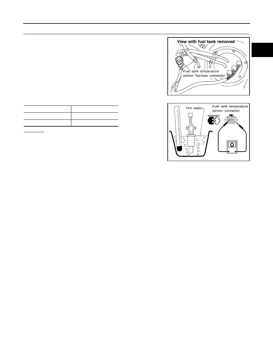
CHECK FUEL TANK TEMPERATURE SENSOR

Check resistance by heating with hot water or heat gun as shown in
the figure.

OK or NG

OK

>> GO TO 19.

NG

>> Replace fuel tank temperature sensor.

SEF334VA

Temperature 

°C (°F)

Resistance k

20 (68)

2.3 - 2.7

50 (122)

0.79 - 0.90

SEF852Z

EC-324

[KA24DE]

DTC P0442 EVAP CONTROL SYSTEM

19. 

CHECK EVAP CONTROL SYSTEM PRESSURE SENSOR

1.

Remove EVAP control system pressure sensor with its harness
connector connected.

2.

Remove hose from EVAP control system pressure sensor.

3.

Use pump to apply vacuum and pressure to EVAP control system pressure sensor as shown in figure.

CAUTION:

Always calibrate the vacuum pump gauge when using it.

Do not apply below 

93.3 kPa (700 mmHg, 27.56 inHg) or over 101.3 kPa (760 mmHg, 29.56

inHg) of pressure.

4.

Check output voltage between ECM terminal 62 and engine
ground.

CAUTION:

Discard any EVAP control system pressure sensor which
has been dropped from a height of more than 0.5 m (19.7 in)
onto a hard surface such as a concrete floor; use a new
one.

OK or NG

OK

>> GO TO 20.

NG

>> Replace EVAP control system pressure sensor.

20. 

CHECK EVAP PURGE LINE

Check EVAP purge line (pipe, rubber tube, fuel tank and EVAP canister) for cracks or improper connection.
Refer to 

EC-565, "EVAPORATIVE EMISSION LINE DRAWING"

 .

OK or NG

OK

>> GO TO 21.

NG

>> Repair or reconnect the hose.

21. 

 CLEAN EVAP PURGE LINE

Clean EVAP purge line (pipe and rubber tube) using air blower.

>> GO TO 22.

22. 

CHECK REFUELING EVAP VAPOR LINE

Check refueling EVAP vapor line between EVAP canister and fuel tank for clogging, kink, looseness and
improper connection. For location, refer to 

EC-570, "ON BOARD REFUELING VAPOR RECOVERY (ORVR)"

.

OK or NG

OK

>> GO TO 23.

NG

>> Repair or replace hoses and tubes.

SEF341V

Applied vacuum kPa (mmHg, inHg)

Voltage [V]

Not applied

1.8 - 4.8

-26.7 (-200, -7.87)

 2.1 to 2.5V lower than above value

SEF198V

DTC P0442 EVAP CONTROL SYSTEM

EC-325

[KA24DE]

C

D

E

F

G

H

I

J

K

L

M

A

EC

23. 

CHECK SIGNAL LINE AND RECIRCULATION LINE

Check signal line and recirculation line between filler neck tube and fuel tank for clogging, kink, cracks, loose-
ness and improper connection.

OK or NG

OK

>> GO TO 24.

NG

>> Repair or replace hoses, tubes or filler neck tube.

24. 

CHECK REFUELING CONTROL VALVE

1.

Remove fuel filler cap.

2.

Check air continuity between hose ends A and B.
Blow air into the hose end B. Air should flow freely into the fuel tank.

3.

Blow air into hose end A and check there is no leakage.

4.

Apply pressure to both hose ends A and B [20 kPa (150 mmHg, 5.91 inHg)] using a pressure pump and a
suitable 3–way connector. Check that there is no leakage.

OK or NG

OK

>> GO TO 25.

NG

>> Replace refueling control valve with fuel tank.

25. 

CHECK FUEL LEVEL SENSOR

1.

Remove fuel level sensor assembly. Refer to 

FL-6, "FUEL LEVEL SENSOR UNIT AND FUEL PUMP

ASSEMBLY"

 .

2.

Refer to.

OK or NG

OK

>> GO TO 26.

NG

>> Replace fuel level sensor.

26. 

CHECK INTERMITTENT INCIDENT

Perform 

EC-120, "TROUBLE DIAGNOSIS FOR INTERMITTENT INCIDENT"

 .

>> INSPECTION END.

DI-18, "FUEL LEVEL SENSOR UNIT CHECK"

SEF707Z

EC-326

[KA24DE]

DTC P0444, P0445 EVAP CANISTER PURGE VOLUME CONTROL SOLENOID 

VALVE

DTC P0444, P0445 EVAP CANISTER PURGE VOLUME CONTROL SOLENOID
VALVE

PFP:14920

Description

UBS00D7G

SYSTEM DESCRIPTION

 This system controls flow rate of fuel vapor from the EVAP canister. The opening of the vapor by-pass pas-
sage in the EVAP canister purge volume control solenoid valve changes to control the flow rate. The EVAP
canister purge volume control solenoid valve repeats ON/OFF operation according to the signal sent from the
ECM. The opening of the valve varies for optimum engine control. The optimum value stored in the ECM is
determined by considering various engine conditions. When the engine is operating, the flow rate of fuel vapor
from the EVAP canister is regulated as the air flow changes.

COMPONENT DESCRIPTION

The EVAP canister purge volume control solenoid valve uses a ON/
OFF duty to control the flow rate of fuel vapor from the EVAP canis-
ter. The EVAP canister purge volume control solenoid valve is
moved by ON/OFF pulses from the ECM. The longer the ON pulse,
the greater the amount of fuel vapor that will flow through the valve.

CONSULT-II Reference Value in Data Monitor Mode

UBS00D7H

Specification data are reference values.

Sensor

Input Signal to ECM

ECM function

Actuator

Camshaft position sensor

Engine speed

EVAP canister 
purge flow control

EVAP canister purge volume 
control solenoid valve

Mass air flow sensor

Amount of intake air

Engine coolant temperature sensor

Engine coolant temperature

Ignition switch

Start signal

Throttle position sensor

Throttle position

Throttle position switch

Closed throttle position

Heated oxygen sensor 1

Density of oxygen in exhaust gas
(Mixture ratio feedback signal)

Fuel tank temperature sensor

Fuel temperature in fuel tank

Vehicle speed sensor

Vehicle speed

SEF337U

MONITOR ITEM

CONDITION

SPECIFICATION

PURG VOL C/V

Engine: After warming up

Air conditioner switch “OFF”

Shift lever: “N”

No-load

Idle (Vehicle stopped)

0%

2,000 rpm


Content   ..  303  304  305  306   ..