Nissan Frontier D22. Manual - part 247


  Index      Nissan     Nissan Frontier D22 Pickup (1998-2004 year) - Service and Repair Manual


Search            


Content   ..  245  246  247  248   ..


Nissan Frontier D22. Manual - part 247


TROUBLE DIAGNOSIS

EC-91

[KA24DE]

C

D

E

F

G

H

I

J

K

L

M

A

EC

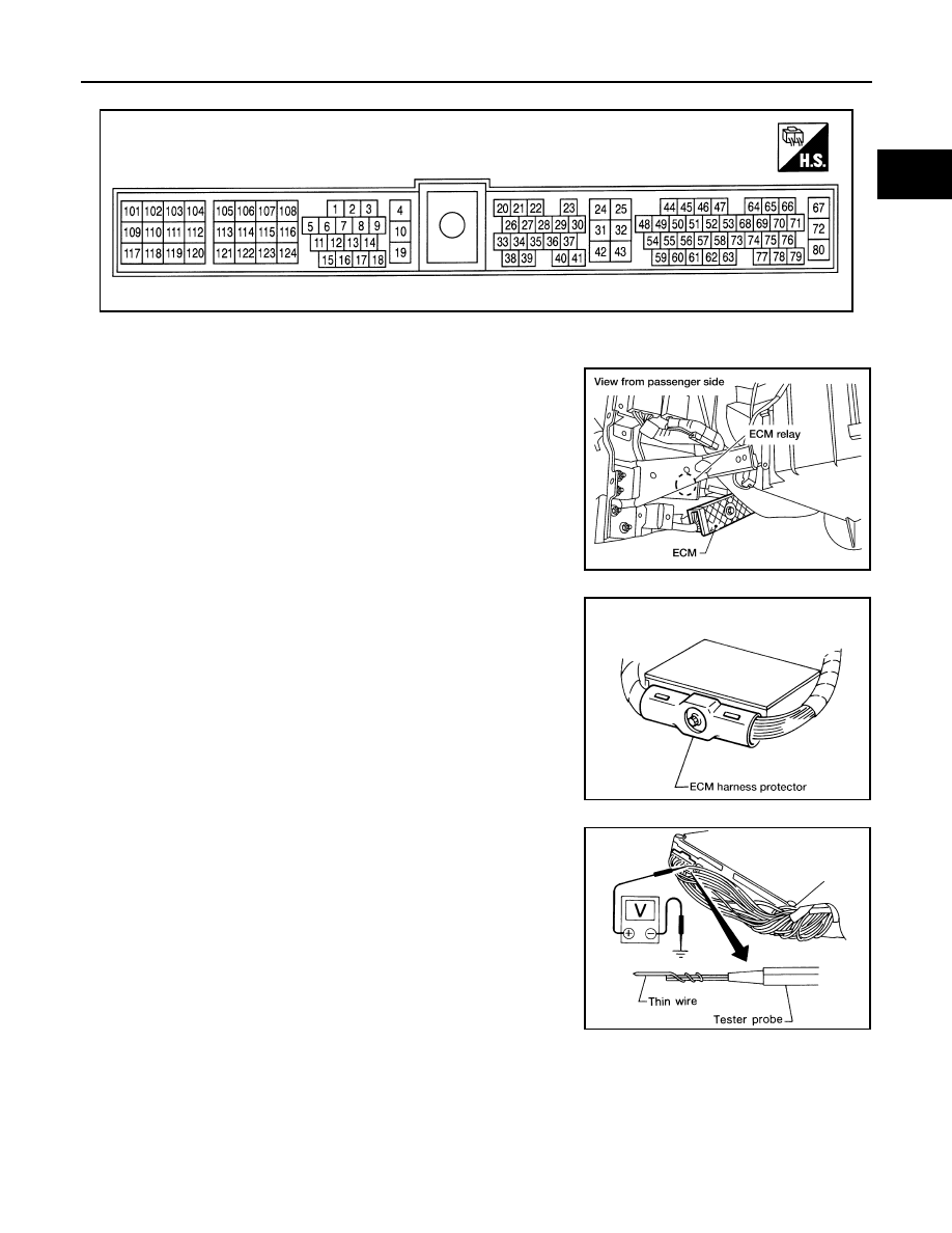
ECM Harness Connector Terminal Layout

UBS00D1J

ECM Terminals and Reference Value

UBS00D1K

PREPARATION

1.

ECM is located behind the instrument lower cover. For this
inspection:

Remove instrument lower cover.

2.

Remove ECM harness protector.

3.

Perform all voltage measurements with the connector con-
nected. Extend tester probe as shown to perform tests easily.

Open harness securing clip to make testing easier.

Use extreme care not to touch 2 pins at 1 time.

Data is for comparison and may not be exact.

ECM INSPECTION TABLE

Specification data are reference values and are measured between each terminal and ground.

CAUTION:

Do not use ECM ground terminals when measuring input/output voltage. Doing so may result in dam-
age to the ECM's transistor. Use a ground other than ECM terminals, such as the ground.

SEF533P

LEC106A

AEC913

MEC486B

EC-92

[KA24DE]

TROUBLE DIAGNOSIS

TER-

MINAL 

NO.

WIRE 

COLOR

ITEM

CONDITION

DATA (DC Voltage)

1

PU/W

Ignition signal

[Engine is running]

Warm-up condition

Idle speed

NOTE:
The pulse cycle changes depending on rpm at 
idle.

0 - 0.5V

[Engine is running]

Warm-up condition

Engine speed is 2,000 rpm

0.2 - 1.0V

2

B

Ignition check

[Engine is running]

Idle speed

NOTE:
The pulse cycle changes depending on rpm at 
idle.

12 - 14V

[Engine is running]

Warm-up condition

Engine speed is 2,000 rpm

12 - 13V

3

P/L

Tachometer

[Engine is running]

Warm-up condition

Idle speed

NOTE:
The pulse cycle changes depending on rpm at 
idle.

0 - 1V

[Engine is running]

Warm-up condition

Engine speed is 2,000 rpm

0.5 - 2V

SEF186T

SEF187T

SEF188T

SEF189T

SEF190T

SEF191T

TROUBLE DIAGNOSIS

EC-93

[KA24DE]

C

D

E

F

G

H

I

J

K

L

M

A

EC

4

LG/R

ECM relay
 (Self shut-off)

[Engine is running]
[Ignition switch: OFF]

For a few seconds after turning ignition switch 
OFF

0 - 1V

[Ignition switch: OFF]

More than a few seconds after turning ignition 
switch OFF

BATTERY VOLTAGE
(11 - 14V)

5

R/Y

EVAP canister purge 
volume control sole-
noid valve

[Engine is running]

Idle speed

BATTERY VOLTAGE

(11 - 14V)

[Engine is running]

Engine speed is 2,000 rpm (More than 200 sec-
onds after starting engine)

12 - 13V

10

B/R

ECM ground

[Engine is running]

Idle speed

Engine ground

11

W/R

Fuel pump relay

[Ignition switch: ON]

For a few seconds after turning ignition switch 
ON.

[Engine is running]

0 - 1V

[Ignition switch: ON]

More than a few seconds after turning ignition 
switch ON

BATTERY VOLTAGE
(11 - 14V) 

12

P

Air conditioner relay

[Engine is running]

Both A/C switch and blower switch are ON*
*: Any mode except “OFF”, ambient air temper-
ature above 10

°C (50°F).

Approximately 0V

[Engine is running]

A/C switch: OFF

BATTERY VOLTAGE
(11 - 14V)

18

R/W

Malfunction indicator 
lamp

[Ignition switch: ON]

0 - 1V

[Engine is running]

Idle speed

BATTERY VOLTAGE
(11 - 14V)

19

B/R

 ECM ground

[Engine is running]

Idle speed

Engine ground

20

L/OR

Start signal

[Ignition switch: ON]

Approximately 0V

[Ignition switch: START]

BATTERY VOLTAGE
(11 - 14V)

TER-

MINAL 

NO.

WIRE 

COLOR

ITEM

CONDITION

DATA (DC Voltage)

SEF109V

SEF110V

EC-94

[KA24DE]

TROUBLE DIAGNOSIS

21

G/R

Air conditioner dual-
pressure switch

[Engine is running]

Both air conditioner switch and blower switch: 
ON (Compressor operates)

Approximately 0V

[Engine is running]

Air conditioner switch: OFF

BATTERY VOLTAGE
(11 - 14V)

22

L/B

Park/neutral position 
(PNP) switch

[Ignition switch: ON]

Shift lever: P or N

Approximately 0V

[Ignition switch: ON]

Except above position

Approximately 5V

23

L

Throttle position sen-
sor

[Ignition switch: ON]

Warm-up condition

Accelerator pedal is fully released

0.2 - 0.8V

[Ignition switch: ON]

Engine stopped

Accelerator pedal is fully depressed

3.5 - 4.5V

24

W/G

Ignition switch

[Ignition switch: OFF]

0V

[Ignition switch: ON]

BATTERY VOLTAGE
(11 - 14V)

25

B/Y

ECM ground

[Engine is running]

Idle speed

Engine ground

28

BR/W

Throttle position 
switch (Closed posi-
tion)

[Ignition switch: ON]

Warm-up condition

Accelerator pedal is fully released

BATTERY VOLTAGE
(11 - 14V)

[Ignition switch: ON]

Engine stopped

Accelerator pedal is slightly depressed

Approximately 0V

29

G/B

Vehicle speed sensor

[Engine is running]

Lift up the vehicle

Shift lever: D (A/T), 2nd (M/T)

Vehicle speed: 40 km/h (25 MPH)

1 - 4V

32

B/Y ECM 

ground

[Engine is running]

Idle speed

Engine ground

39

GY/R

Power steering oil 
pressure switch

[Engine is running]

Steering wheel is fully turned

Approximately 0V

[Engine is running]

Steering wheel is not turned

Approximately 5V

42

BR

Sensor power supply

 [Ignition switch: ON]

Approximately 5V

43

B/W

Sensor ground

[Engine is running]

Idle speed

Approximately 0V

TER-

MINAL 

NO.

WIRE 

COLOR

ITEM

CONDITION

DATA (DC Voltage)

SEF111V


Content   ..  245  246  247  248   ..