Nissan Frontier D22. Manual - part 244


  Index      Nissan     Nissan Frontier D22 Pickup (1998-2004 year) - Service and Repair Manual


Search            


Content   ..  242  243  244  245   ..


Nissan Frontier D22. Manual - part 244


TROUBLE DIAGNOSIS

EC-79

[KA24DE]

C

D

E

F

G

H

I

J

K

L

M

A

EC

10. 

ADJUSTMENT THROTTLE POSITION SENSOR IDLE POSITION-3

 With CONSULT-II

1.

Temporarily tighten sensor body fixing bolts as follows.

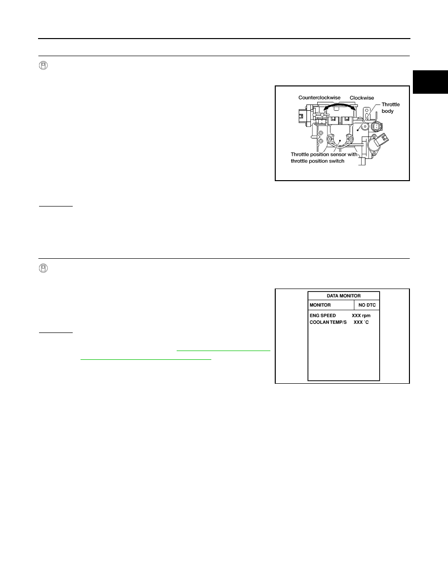
Gradually move the sensor body clockwise and stop it
when “CLSD THL/P SW” signal switches from “OFF” to
“ON” when tightening sensor body fixing bolts.

2.

Make sure two or three times that the signal is “ON” when the
throttle valve is closed and “OFF” when it is opened.

3.

Remove 0.1 mm (0.004 in) feeler gauge then insert 0.3 mm
(0.012 in) feeler gauge.

4.

Make sure two or three times that the signal remains “OFF”
when the throttle valve is closed.

5.

Tighten throttle position sensor.

6.

Check “CLSD THL/P SW” signal again.
The signal remains “OFF” while closing throttle valve.

OK or NG

OK

>> 1. Remove 0.3 mm (0.012 in) feeler gauge.

2. GO TO 11.

NG

>> GO TO 8.

11. 

CHECK TARGET IDLE SPEED

 With CONSULT-II

1.

Start engine and warm it up to normal operating temperature.

2.

Select “ENG SPEED” in “DATA MONITOR” mode.

3.

Check idle speed.

OK or NG

OK

>> INSPECTION END

NG

>> Adjust idle speed. Refer to 

EC-36, "Idle Speed/Ignition

Timing/Idle Mixture Ratio Adjustment"

 . Inspection end

after adjust idle speed.

AEC872A

800

±50 rpm (in P or N position)

SEF174Y

EC-80

[KA24DE]

TROUBLE DIAGNOSIS

12. 

CHECK IGNITION TIMING

 Without CONSULT-II

1.

Warm up engine to normal operating temperature.

2.

Stop engine and disconnect throttle position sensor harness
connector.

3.

Start engine.

4.

Rev engine (2,000 to 3,000 rpm) two or three times under no-
load and then run engine at idle speed.

5.

Check ignition timing at idle using timing light.

OK or NG

OK

>> GO TO 13.

NG

>> 1. Adjust ignition timing by turning distributor. Refer to

EC-36, "Idle Speed/Ignition Timing/Idle Mixture Ratio
Adjustment"

 .

2. GO TO 13.

13. 

CHECK BASE IDLE SPEED

 Without CONSULT-II

Make sure that engine speed falls to the following speed.

OK or NG

OK

>> GO TO 14.

NG

>> 1. Adjust base idle speed by turning idle speed adjusting screw. Refer to 

EC-36, "Idle Speed/Igni-

tion Timing/Idle Mixture Ratio Adjustment"

 .

2. GO TO 14.

SEF265S

Ignition timing

: 20

°±2° BTDC (in P or N position)

SEF320V

750

±50 rpm (in P or N position)

TROUBLE DIAGNOSIS

EC-81

[KA24DE]

C

D

E

F

G

H

I

J

K

L

M

A

EC

14. 

CHECK CLOSED THROTTLE POSITION SWITCH IDLE POSITION (CHECK THROTTLE POSITION 

SENSOR IDLE POSITION)

 Without CONSULT-II

NOTE:
Always check ignition timing and base idle speed before performing the following.
1.

Warm up engine to normal operating temperature.

2.

Check FI cam. Refer to procedure 4.

3.

Stop engine.

4.

Disconnect closed throttle position switch harness connector.

5.

Connect the tester probe to closed throttle position switch terminals 5 and 6.

6.

Check harness continuity under the following conditions.

Insert the 0.1 mm (0.004 in) and 0.3 mm (0.012 in) feeler gauge
alternately between the throttle adjust screw (TAS) and throttle
drum as shown in the figure.
 “Continuity should exist” while inserting 0.1 mm (0.004 in)
feeler gauge.
“Continuity should not exist” while inserting 0.3 mm (0.012
in) feeler gauge.

OK or NG

OK

>> GO TO 18.

NG

>> GO TO 15.

SEF862V

BBIA0428E

EC-82

[KA24DE]

TROUBLE DIAGNOSIS

15. 

ADJUSTMENT THROTTLE POSITION SENSOR IDLE POSITION-1

 Without CONSULT-II

NOTE:

Never adjust throttle adjust screw (TAS).

Do not touch throttle drum when checking “continuity”.
Doing so may cause an incorrect adjustment.

1.

Warm engine up to normal operating temperature.

2.

Check FI cam. Refer to procedure 4.

3.

Stop engine.

4.

Loosen throttle position sensor fixing bolts.

5.

Disconnect closed throttle position sensor harness connector.

6.

Insert 0.1 mm (0.004 in) feeler gauge between the throttle adjust
screw and throttle drum as shown in the figure.

7.

Open throttle valve then close.

8.

Check continuity between closed throttle position switch termi-
nal 5 and 6.
The continuity should not exist while closing the throttle
position sensor body.
If it is impossible to adjust closed throttle position switch, replace
throttle position sensor.

OK or NG

OK

>> GO TO 17.

NG

>> GO TO 16.

16. 

ADJUSTMENT THROTTLE POSITION SENSOR IDLE POSITION-2

 Without CONSULT-II

Turn throttle position sensor body counterclockwise until continuity
does not exist.

>> GO TO 17.

BBIA0428E

SEF862V

AEC872A


Content   ..  242  243  244  245   ..