Nissan Frontier D22. Manual - part 215


  Index      Nissan     Nissan Frontier D22 Pickup (1998-2004 year) - Service and Repair Manual


Search            


Content   ..  213  214  215  216   ..


Nissan Frontier D22. Manual - part 215


METERS AND GAUGES

DI-9

C

D

E

F

G

H

I

J

L

M

A

B

DI

Meter/Gauge Operation and Odo/Trip Meter Segment Check in Diagnosis Mode

EKS006W8

DIAGNOSIS FUNCTION

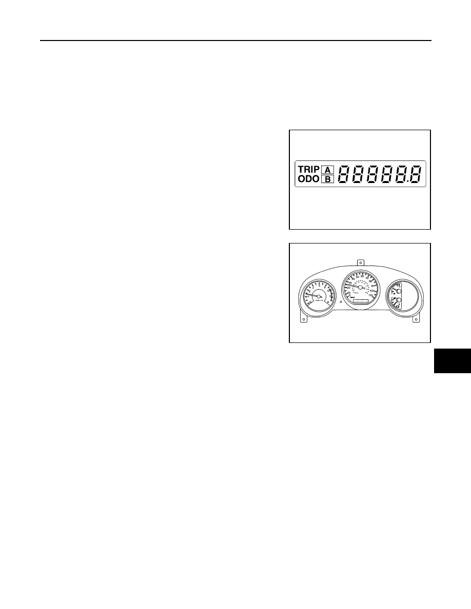
Odo/trip meter segment can be checked in diagnosis mode.

Meters/gauges can be checked in diagnosis mode.

HOW TO ALTERNATE DIAGNOSIS MODE

1.

Turn ignition switch ON, while pressing and holding the trip reset switch for 0.8 second.

2.

Push trip reset switch 3 times within 7 seconds.

3.

All odo/trip meter segments should be turned on.
NOTE:
If some segments are not turned on, the combination meter
should be replaced.
At this point, the combination meter is in diagnosis mode.

4.

Push odo/trip meter switch. Indication of each meter/gauge
should be as shown in figure at left while pushing odo/trip meter
switch.

NOTE:
It takes about 1 minute for the fuel gauge indication to  sta-
bilize.

SEL110V

WEL900A

DI-10

METERS AND GAUGES

Trouble Diagnoses

EKS006W9

PRELIMINARY CHECK

*1:

DI-9

*2:

DI-12

*3:

DI-11

WEL835A

METERS AND GAUGES

DI-11

C

D

E

F

G

H

I

J

L

M

A

B

DI

SYMPTOM CHART

Before starting trouble diagnoses above, perform 

DI-10, "PRELIMINARY CHECK"

 .

Symptom

Possible causes

Repair order

Speedometer and odo/trip 

meter are malfunctioning.

1. Signal

Speedometer and odo/trip meter

2. Unified meter control unit

1. Check vehicle speed sensor.

Refer to 

DI-13, "INSPECTION/VEHICLE SPEED SEN-

SOR"

 .

2. Replace combination meter.

Multiple meters/gauges 
(except speedometer and 
odo/trip meter) are malfunc-
tioning.

Unified meter control unit

Replace combination meter.

One gauge (tachometer, 
fuel gauge, or water temp. 
gauge) is malfunctioning.

Unified meter control unit

Replace combination meter.

DI-12

METERS AND GAUGES

POWER SUPPLY AND GROUND CIRCUIT CHECK
Power Supply Circuit Check

If NG, check the following.

7.5A fuse [No. 28, located in fuse block (J/B)]

10A fuse [No. 11, located in fuse block (J/B)]

Harness for open or short between fuse and combination meter

Ground Circuit Check

Terminals

Ignition switch position

(+)

(

−)

Connector

Terminal

(Wire color)

OFF

ACC

ON

M39

31 (R/Y)

Ground

Battery 
voltage

Battery 
voltage

Battery 
voltage

M39

32 (W/B)

0V

0V

Battery 
voltage

WEL791A

Terminals

Continuity

( + )

( – )

Connector

Terminal

(Wire color)

M39

33 (B/R)

Ground

Yes

WEL792A


Content   ..  213  214  215  216   ..